Note: This article is written for educational and engineering analysis purposes. It explains real-world techniques used to study undocumented LED protocols, without copying protected source material or requiring readers to use any proprietary code.
Introduction: When Two Wires Do More Than They Should
At first glance, a two-wire LED strip looks boring. One wire is positive, the other is ground, and the LEDs turn on. Case closed, right? Not quite. Some modern decorative LED strings, especially curtain lights and tiny “fairy light” style RGB strands, can change colors by zone, run animations, and respond to a remote control while still using only two conductors across the whole string. That tiny fact is enough to make any hardware hacker stop mid-coffee and ask the dangerous question: “Wait… how?”
Reverse-engineering a two-wire LED strip protocol is the process of figuring out how data is being transmitted when there appears to be no separate data wire. Unlike a typical WS2812B LED strip, which uses power, ground, and a dedicated data line, these strips often send control information through the same pair of wires that powers the LEDs. In other words, the power line is not just feeding the circuit; it is also whispering instructions. Very rudely, too, because it usually does this by being yanked low in carefully timed pulses.
This makes the protocol wonderfully strange. It is simple, cheap, clever, and a little bit chaoticthe electronic equivalent of sending Morse code by flicking the kitchen lights off and on. Yet behind the apparent weirdness is a smart engineering compromise: fewer wires, cheaper manufacturing, simpler copper strings, and enough control to create colorful animations that look far more complex than the hardware deserves.
What Makes A Two-Wire LED Protocol Different?
Most addressable LED systems are easy to categorize. A WS2812B or SK6812 style strip normally has three connections: voltage, ground, and one self-clocking data signal. APA102 or DotStar style LEDs use a clock and data line, plus power and ground, making them easier to drive at high speeds but requiring more conductors. Analog RGB strips may have four pads labeled for red, green, blue, and voltage, but those are not individually addressable; the entire strip changes together.
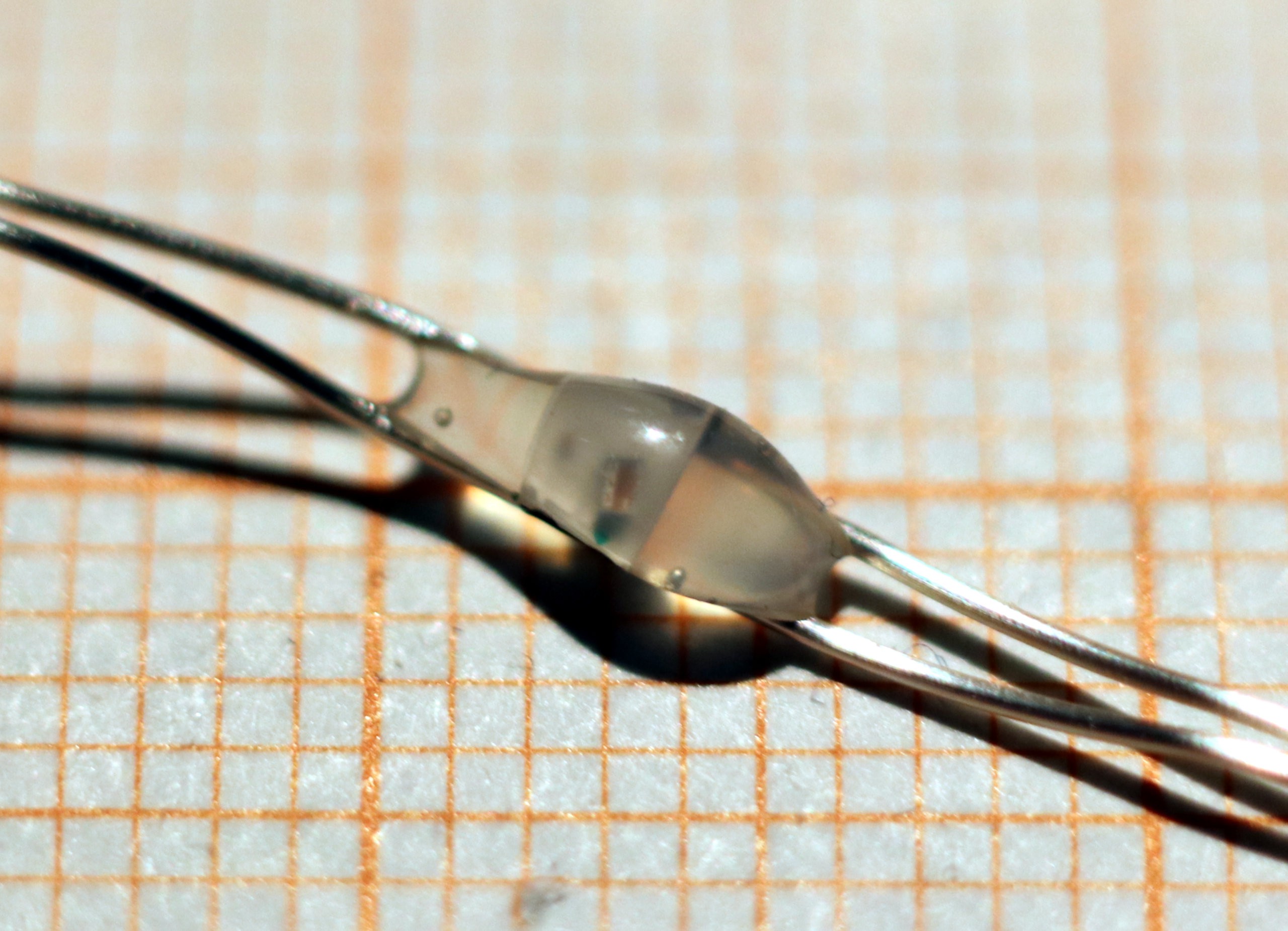
A true two-wire addressable LED string is different. Every LED is connected in parallel across the same two rails. There is no daisy-chained data path from one LED package to the next. Instead, each LED contains a tiny integrated circuit that watches the supply voltage itself. When the controller briefly shorts or pulls down the supply, the LED chip interprets those voltage interruptions as information.
The trick is state retention. If the controller pulls power low for only a very short time, the LED driver chip can survive the dip using tiny internal capacitance or a small local charge reservoir. The visible LED may blink off for microseconds, but the chip does not completely forget who it is or what command it was receiving. That allows the power rail to double as a crude communication bus.
The Basic Reverse-Engineering Setup
Reverse-engineering this kind of protocol does not begin with heroic firmware extraction or microscope-level chip surgery. It begins with patience, measurement, and the willingness to stare at waveforms until they stop looking like barcode soup.
Useful Tools
A digital oscilloscope is the first major tool because the signal is fundamentally an analog voltage event: the supply rail gets pulled low, released, pulled low again, and so on. A logic analyzer can help once voltage levels are safe and the signal has been conditioned, but an oscilloscope is better for seeing pulse width, voltage droop, ringing, and whether the rail actually reaches ground.
A current-limited bench power supply is also helpful. Unknown LED strings can draw more current than expected, and a current limit can save both the lights and your pride. A photodiode or light sensor can add another layer of insight by showing when the LED output actually changes relative to the electrical command. That matters because the visible update may happen after the final pulse, not during the pulse train itself.
Safe First Measurements
The safest first move is to observe the original controller rather than immediately replacing it. Connect the LED string to its factory controller, place the oscilloscope probe across the two LED wires, and trigger on falling edges. Then press buttons on the remote: red, green, blue, white, animation mode, brightness, and power. Each button press becomes a clue.
Common patterns begin to appear. A color-change command may start with a reset or clearing sequence, followed by a series of shorter command frames. Some frames control one zone, while others broadcast to all zones. A long pause may mark the end of a command, while a shorter pause may separate an address field from a data field. At this point, you are not “decoding” yet. You are collecting sightings of the protocol in the wild, like a patient wildlife photographer, except the animal is a suspicious Christmas light.
How The Protocol Often Works
In one well-known analyzed design, the controller sends data by pulling the entire LED supply voltage to ground for short durations. The message is not encoded as a normal binary stream. Instead, it can use pulse counting: one group of pulses represents an address, a pause separates fields, and another group of pulses represents color data.
That means the receiver does not necessarily read “10110010” the way a WS2812-style device might. It may simply count events. For example, after a starting pulse, the number of following pulses can represent a zone address. A second pulse group can represent the data value. The data value may not be full 24-bit RGB brightness either. It may be only three bits: red on or off, green on or off, and blue on or off. That gives eight states: off, red, green, yellow, blue, magenta, cyan, and white.
This explains why many inexpensive two-wire RGB strings can show bright solid colors and simple animations but not silky smooth gradients on every individual LED. The hardware is not trying to be a full NeoPixel clone. It is trying to create attractive lighting effects at extremely low cost. The engineering goal is not “maximum color fidelity.” It is “make the living room look festive without adding another wire.”
Address Fields, Data Fields, And Zones
A practical two-wire LED protocol may divide the string into groups rather than controlling every LED independently. For instance, a curtain light might contain several zones distributed across the physical strand. The controller can send a command to zone 1, zone 2, zone 3, and so on, or use a broadcast command that affects all groups.
This architecture is clever because it creates the illusion of animation without needing hundreds of unique LED addresses. If six zones are scattered throughout a curtain, changing one zone at a time creates movement. The viewer sees twinkling, waves, and color shifts. The hardware sees only a handful of zone commands.
Reverse-engineering the address system requires comparing captures. Send red, then green, then blue. Send a built-in animation and watch whether the same pulse counts repeat. If a command with five pulses always changes the same physical group, you have likely found a zone address. If a command changes the whole strip, it may be a broadcast or global operation.
Timing: The Secret Sauce
Timing is everything in a two-wire LED strip protocol. The pulse width must be long enough for the LED chip to detect a low event but short enough that the chip does not fully lose power. The high interval must be long enough to recharge whatever internal or external capacitance keeps the receiver alive. The pauses must be distinct enough to separate fields and frames.
Many low-cost controllers derive timing from simple clocks, such as a watch crystal or inexpensive microcontroller oscillator. That can produce pulse periods in the tens of microseconds. A reverse engineer should measure not only the low time but also the high time, the field gap, and the frame gap. These values form the grammar of the protocol.
One especially interesting design behavior is adaptive timeout detection. Instead of using a fixed internal clock, the LED chip may measure the previous high interval and use a related delay to decide when a field has ended. That lets the same basic chip tolerate different pulse speeds. From a manufacturing perspective, this is excellent: fewer precision requirements, less trimming, and more tolerance for cheap silicon. From a reverse-engineering perspective, it is a reminder that “simple” circuits can be sneakily elegant.
Why Not Just Use WS2812B?
WS2812B LEDs are famous because they provide individual RGB control with only one data wire in addition to power and ground. They are widely supported by Arduino libraries, ESP32 projects, WLED installations, and hobbyist tools. So why would anyone invent a stranger two-wire powerline approach?
The answer is manufacturing cost and mechanical simplicity. Copper string lights are often made as two long conductors with LED packages attached across them. Adding a third conductor or daisy-chained data routing would change the manufacturing process. For cheap decorative products, that change matters. A two-wire protocol lets manufacturers keep the simple string construction while adding just enough intelligence inside each LED package.
There are tradeoffs. WS2812-style LEDs can control many pixels with 24-bit color data per LED. APA102-style LEDs can use clocked data and achieve high refresh rates with less timing stress on the microcontroller. Two-wire powerline-controlled LEDs usually offer less precision, fewer colors, and lower practical refresh rates. But for holiday lights, costumes, props, small art installations, and low-cost ambient effects, “good enough” can be commercially brilliant.
Decoding A Capture Step By Step
Step 1: Record Known Actions
Start by capturing the waveform for simple commands. Press red and save the trace. Press green and save the trace. Press blue, white, off, and one animation mode. Name the files clearly. Future you will not remember that “scope_17_final_FINAL2.csv” was the cyan button. Future you is a liar with poor file hygiene.
Step 2: Identify Repeated Structures
Look for repeated pulse groups. A command frame might always begin with a single pulse. A short pause may always appear between two groups. A longer pause may separate commands. Measure these gaps. If the same structure appears across multiple colors, you have found the message format.
Step 3: Compare Color Values
If red, green, and blue commands differ only in the second field, that field is probably data. If yellow appears as red plus green, or as rapid alternation between red and green, you can infer how the controller creates mixed colors. Some systems may use direct RGB bit combinations, while others use temporal mixing to reduce brightness or current consumption.
Step 4: Map Physical Zones
Send suspected address values one by one and observe which LEDs change. If LEDs are molded or distributed irregularly, mark them with tape or photograph the string after each command. A zone map turns a mysterious protocol into a controllable system.
Step 5: Recreate The Signal
Once the timing and frame structure are known, a microcontroller can reproduce the waveform. For short strings, a GPIO pin may be enough for experiments, but larger strings should use a MOSFET or proper driver stage because the same line supplies LED current. Pulling a long LED string low directly from a microcontroller pin is a fine way to convert a development board into a tiny smoke machine.
Electrical Design Considerations
The output stage is not just a data driver. It is a power switch. That means current handling, voltage drop, MOSFET selection, rise time, and wiring inductance all matter. A low-side switch can pull the rail down to create pulses, but the LED string must recover quickly and cleanly. Slow edges may blur pulse timing. Excessive ringing may create false pulses. Long strings can behave like antennas, which is charming only if your hobby is debugging problems that appear when someone walks near the cable.
Adding a series resistor, snubber, or careful layout may improve signal quality. A scope probe should be connected near the LED string as well as near the controller, because the waveform at the far end may differ from the waveform at the driver. If the protocol is based on pulse counting, false edges are deadly. If it is based on pulse width, edge distortion can shift decoded values.
What This Teaches About Embedded Design
The two-wire LED strip protocol is a beautiful lesson in constraint-driven engineering. The designer had almost nothing to work with: no data line, minimal silicon area, tiny packages, low cost, and a product that needed to survive mass manufacturing. The solution was not to imitate a high-end addressable LED. The solution was to exploit the one shared resource every LED already had: power.
For engineers and makers, this is a reminder that protocols are not always elegant in the textbook sense. Some are practical, weird, and optimized for a factory line rather than a standards committee. Reverse engineering such systems teaches you to observe before assuming. Not every pulse train is UART. Not every addressable LED is WS2812. Not every “bad” design is actually bad. Sometimes it is a very good design wearing cheap plastic shoes.
Common Mistakes When Reverse-Engineering Two-Wire LEDs
Assuming It Is A Normal Data Bus
The first mistake is searching for a missing data line. In a true two-wire powerline protocol, the data is not hidden on a third conductor. It is embedded in the power behavior. Look at voltage interruptions, not serial bytes.
Sampling Too Slowly
Microsecond pulses require adequate sample rate. If your scope or logic analyzer settings are too slow, the protocol may appear random or incomplete. Capture faster than you think you need, then zoom out later.
Ignoring The Optical Output
The electrical command and visible LED update are related but not identical. A photodiode can reveal update delays, PWM behavior, and whether color mixing is done by direct channel control or rapid alternation.
Overdriving The String
Because the communication line is also the power line, experiments can affect LED brightness, current, and chip stability. Use current limits, start with short strings, and avoid connecting unknown LED products directly to expensive boards without a driver.
Practical Example: Reconstructing A Simple Command
Imagine a captured command where the controller sends one start pulse, four address pulses, a short pause, one start pulse, and three data pulses. After a longer pause, one group of LEDs turns blue. Repeating the test with two data pulses turns the same group green, while one data pulse turns it red. That strongly suggests the first field selects the zone and the second field selects the color value.
Now imagine a command with a special address value that affects every zone. If the data field is added to each zone’s current color latch rather than replacing it, the controller can produce global color changes with fewer pulses. That kind of shortcut is exactly what you might expect in a low-speed protocol where every pulse costs time and every long update risks visible flicker.
Once these rules are known, the mystery product becomes programmable. You can build a replacement controller, generate custom animations, synchronize the lights with music, or simply enjoy the satisfaction of making an undocumented device obey your own code. That is the good kind of power trip.
Experience Notes: What It Feels Like To Reverse-Engineer This Protocol
Working on a two-wire LED strip protocol feels less like reading a data sheet and more like interviewing a very secretive machine. It answers every question with a waveform. Ask, “What does red mean?” and it gives you a cluster of pulses. Ask, “What does animation mode do?” and it dumps a long, repetitive sequence that looks like the controller is nervously tapping its foot. The fun begins when those taps become language.
The first experience lesson is to slow down. Beginners often want to write replacement firmware immediately, but the fastest path is careful observation. Capture the original controller doing boring things. Solid red is better than rainbow chase. Power off is better than sparkle mode. Simple commands reveal the frame format; complex animations only make sense after the alphabet is known.
The second lesson is that labels matter. Every capture should have a plain English name: “all_red_button,” “zone_animation_blue_wave,” “remote_power_off,” and so on. Reverse engineering creates many tiny pieces of evidence, and messy notes can ruin a good session. The protocol may be simple, but your future confusion will be advanced.
The third lesson is to trust measurements more than assumptions. If you come from WS2812 projects, you may expect binary color frames and strict bit timing. A two-wire decorative string may instead use pulse counts, zone latches, and crude RGB combinations. If you come from SPI LEDs, you may look for clock edges. There may be no clock line at all, only power interruptions that the chip interprets internally.
The fourth lesson is that cheap products can be intellectually impressive. It is easy to laugh at an inexpensive light string until you realize the design eliminated a data conductor, avoided a complicated PCB chain, fit a controller into each LED package, and still produced animations attractive enough for consumers. That is not sloppy engineering. That is ruthless optimization.
The fifth lesson is to build your replacement controller incrementally. First reproduce a single pulse. Then reproduce one command. Then control one color. Then map zones. Only after that should you attempt custom effects. A small MOSFET driver, a current-limited supply, and a repeatable timing function are more valuable than a giant software framework at the beginning.
Finally, the most satisfying moment is when the unknown strip responds to your own signal for the first time. One LED group changes color, and suddenly the product is no longer a sealed consumer gadget. It is a system you understand. Maybe not perfectly, maybe not at the silicon level, but enough to speak its language. That is the real reward of reverse engineering: turning “How is this possible?” into “I know exactly why this worksand now I can make it do something ridiculous.”
Conclusion
Reverse-engineering a two-wire LED strip protocol reveals how much creativity can hide inside inexpensive consumer electronics. By modulating the power line with carefully timed pulses, a controller can address LED groups, send color commands, and create animations without a separate data wire. The result is not as flexible as a full WS2812B or APA102 system, but it is clever, low-cost, and surprisingly capable.
For makers, this topic is more than a curiosity. It is a practical lesson in measurement, signal timing, embedded constraints, and hardware humility. The best reverse-engineering work begins with a scope probe, clean notes, and a willingness to let the circuit explain itself. Sometimes the protocol is not hidden in firmware or locked inside an app. Sometimes it is pulsing right there on the power rail, waiting for someone nosy enough to notice.