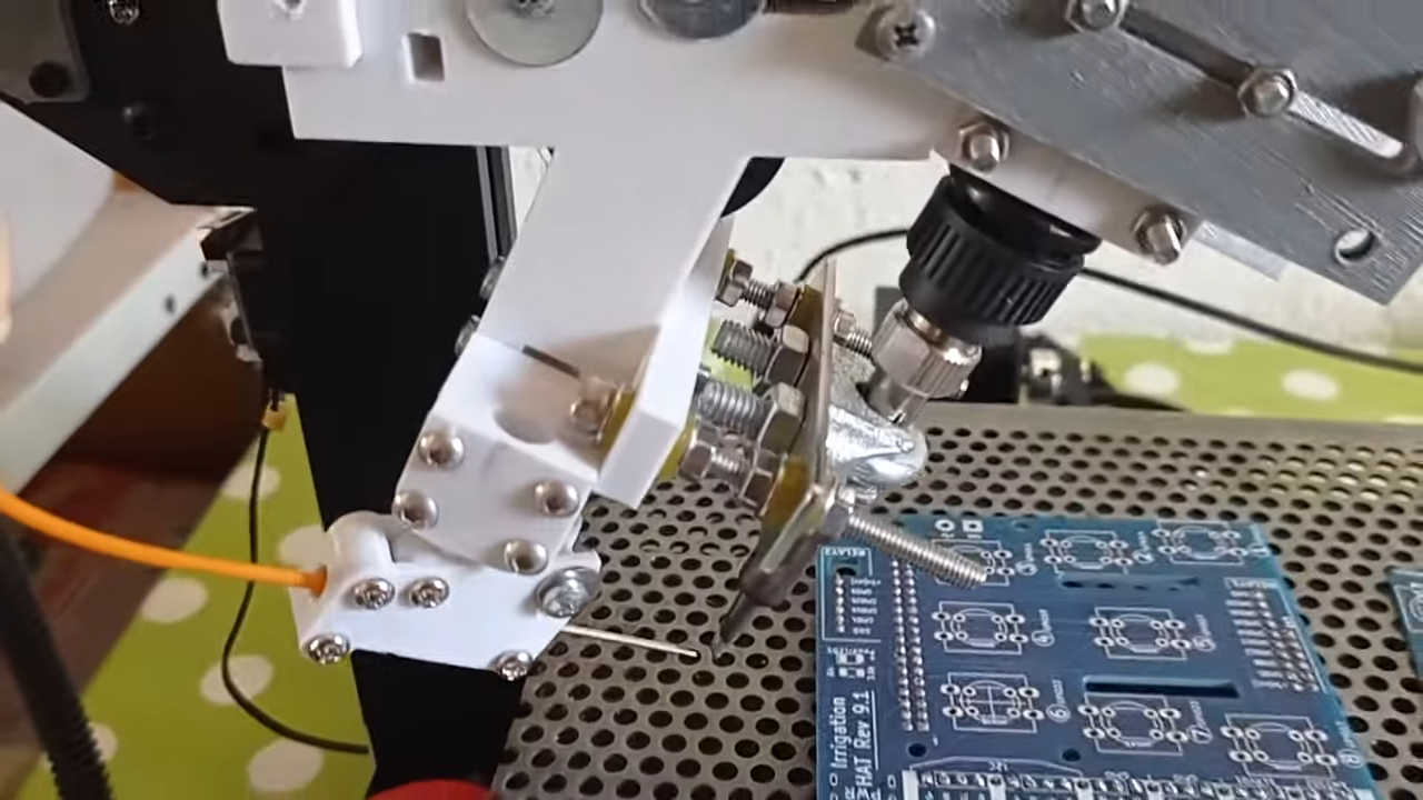
A desktop 3D printer normally spends its days squeezing molten plastic into increasingly ambitious shapes. Give the same machine a soldering iron, a wire feeder, and a carefully programmed toolpath, however, and it can trade plastic dinosaurs for automated PCB assembly. That is the clever idea behind a modified 3D-printer that solders through-hole components one joint at a time.
The conversion works because a 3D printer is already a programmable three-axis robot. Its controller knows how to move a tool to precise X, Y, and Z coordinates, pause for a defined period, and advance material through an extruder. Replace the hot end with a soldering iron, substitute solder wire for filament, and the machine gains an entirely new occupation. It will not demand a promotion, although it may develop expensive taste in clean soldering tips.
How a 3D Printer Becomes an Automatic Soldering Robot
The fundamental conversion is surprisingly straightforward. The printer retains its frame, stepper motors, motion system, control board, and firmware. Instead of printing an object layer by layer, it moves a soldering tool from one plated through-hole joint to the next.
The XYZ Gantry Provides the Robot
Consumer fused-filament fabrication printers already offer repeatable positioning over a useful work area. Their gantries can approach a coordinate, lower a tool, pause, and move away in a predictable sequence. Those movements are exactly what an automated soldering operation needs.
Standard G-code commands can control most of the process. Linear moves position the iron, extrusion values advance solder wire, and dwell commands create short pauses for heating and wetting. Travel speeds can be reduced near the circuit board so the tool does not swoop toward a connector pin like a caffeinated woodpecker.
The Extruder Becomes a Solder-Wire Feeder
A typical printer extruder grips plastic filament with a toothed drive gear. In the modified machine, that mechanism is adapted to push thin solder wire instead. The solder may travel through a guide tube positioned near the iron tip, much like filament traveling through a Bowden tube.
This arrangement gives the controller direct command over the amount of solder supplied to each joint. An extrusion move that once delivered a few millimeters of plastic can instead dispense a measured length of flux-cored solder wire. Retraction can pull the wire back slightly after a joint, helping prevent drips, strings, and unexpected silver decorations on neighboring pads.
A Custom Bracket Holds the Iron
The plastic-printing hot end is replaced or supplemented by a bracket that holds a temperature-controlled soldering iron. An angled mounting position often works well because it resembles the way a technician naturally presents a chisel tip to a pad and component lead.
The bracket must be rigid enough to prevent movement at the tip while keeping heat away from belts, printed parts, wiring, and the carriage. A small amount of flex at the mount can translate into a large positioning error at the end of the iron. That is not ideal when two neighboring connector pins are separated by only a few millimeters.
The Real Secret Is Not the RobotIt Is the Fixture
The most important part of the setup may be the least glamorous: the jig that holds the components and printed circuit board. A robot can revisit the same coordinates all afternoon, but those coordinates are useless if the next board sits half a millimeter to the left.
In a practical arrangement, 3D-printed fixtures hold connectors or other through-hole parts with their pins facing upward. The PCB is placed over those pins and registered against locating features. This keeps the components seated while exposing the solder side of the board to the iron.
A good fixture performs several jobs at once:
- It establishes a repeatable origin for every PCB.
- It prevents components from rising when the iron touches a lead.
- It keeps the board flat and stable while solder solidifies.
- It protects nearby parts from accidental contact.
- It allows fast loading and unloading during small production runs.
This is why fixturing often determines whether the machine is a useful manufacturing tool or merely a fascinating video. Motion accuracy cannot compensate for a board that arrives in a slightly different position every cycle.
Why Automate Through-Hole Soldering?
Through-hole components remain common where mechanical strength, large connectors, switches, relays, transformers, terminal blocks, and high-current connections matter. These parts are easy to understand and friendly to prototypes, but soldering hundreds of identical pins by hand becomes repetitive.
Large factories solve the problem with wave or selective soldering equipment. Wave soldering carries the underside of a board across molten solder, while industrial selective soldering systems apply flux, preheat the assembly, and bring a programmable solder fountain to individual locations. Those systems can be fast and repeatable, but they also require significant floor space, process control, maintenance, and capital.
A modified 3D-printer occupies the middle ground. It is not intended to compete with a full production line. It offers an accessible form of robotic iron soldering for workshops assembling prototypes, test fixtures, educational kits, open-source hardware, or limited batches of the same PCB.
The machine is especially attractive when a board contains only a few through-hole parts after its surface-mount components have been assembled. Instead of exposing the entire underside to a solder wave, the robotic iron can visit only the required joints.
A Typical Automated Soldering Cycle
Once the PCB and components are secured, the machine can follow a programmed routine:
- Home the axes. The printer establishes known mechanical reference positions.
- Move to a safe height. The iron travels above clips, fixtures, and component leads.
- Approach the first joint. The tool slows before contacting the pad and lead.
- Apply heat. The iron touches both conductive surfaces so they warm together.
- Feed solder. The extruder advances a calibrated length of solder wire into the heated joint.
- Allow wetting and flow. A short dwell gives the solder time to fill the connection and form a fillet.
- Retract the wire. A small reverse move reduces trailing solder.
- Lift the iron. The joint cools without being disturbed.
- Travel to the next coordinate. The process repeats until the board is complete.
The exact timing varies with pad size, copper area, lead diameter, tip geometry, solder alloy, flux chemistry, and board construction. A large terminal connected to a ground plane may need more thermal energy than a small header pin. Treating every joint identically is convenient, but convenience and physics are not always on speaking terms.
Key Engineering Challenges
Coordinate Calibration
The first challenge is teaching the machine where every joint is located. A simple system can use manually measured coordinates. More advanced software could import pad locations from PCB design files and translate them into machine coordinates.
The builder must account for the physical offset between the printer carriage, iron tip, and solder-wire outlet. Tool length can also change when the tip is replaced. A reliable workflow therefore needs a repeatable method of setting the board origin and verifying the tool offset before every batch.
Controlled Heat Transfer
Good soldering requires heating both the component lead and the copper pad. Feeding solder directly onto a hot tip may melt the wire without adequately warming the joint, producing a rounded blob that looks impressive from across the room and suspicious under magnification.
The iron temperature, tip shape, contact angle, pressure, and dwell time must be tuned together. A broad chisel tip usually transfers heat more effectively than an extremely fine conical tip. Excessive temperature or dwell can damage pads, discolor the board, degrade flux, or shorten tip life. Too little heat produces poor wetting and unreliable joints.
Consistent Solder Feeding
Solder wire is softer and more easily deformed than common printing filament. The drive gear must grip it without crushing, shaving, or buckling it. The guide path should be smooth, and the final outlet should place the wire against the heated joint rather than into the side of the iron holder.
Flux-cored wire is particularly useful because flux promotes wetting and helps remove surface oxides. Wire diameter also matters. Thin solder allows finer dosage, while thicker wire can deliver material quickly but may be harder to control on closely spaced pins.
Board and Component Variation
Manufactured PCBs have dimensional tolerances, and inexpensive components do not always arrive with perfectly straight leads. A connector that fits tightly on one board may lean slightly on another. The system needs enough mechanical compliance to tolerate minor variation without losing accuracy.
Spring-loaded tool mounts, floating fixtures, tapered locating pins, and replaceable nests can improve repeatability. Camera-based alignment would provide another level of correction by locating fiducials before soldering begins.
Inspection and Quality Control
Automation does not eliminate inspection. It makes inspection more important because one programming error can reproduce the same defect across an entire batch with admirable consistency.
Completed joints should be checked for proper wetting, adequate solder, full coverage, bridging, disturbed surfaces, excessive residue, and damaged pads. Electrical continuity testing can detect open circuits and shorts, but visual inspection remains valuable because an electrically functional joint may still be mechanically weak.
Building a Modified 3D-Printer Soldering System
Choose a Suitable Donor Printer
A basic Cartesian printer is often easier to convert than a compact machine with a heavily integrated toolhead. The frame should be rigid, the axes should move smoothly, and the controller should accept ordinary G-code. A removable or easily modified carriage makes mounting the soldering tool much simpler.
Design the Iron Mount
The mount should position the tip at a practical angle while leaving space for the solder feed tube. Heat-resistant materials and metal hardware are preferable near the iron. Printed plastic components should be separated from the heated barrel and protected from prolonged radiant heat.
Modify the Feeder Carefully
The extruder should advance solder smoothly at low speed. A less aggressive drive profile may be necessary to avoid flattening the wire. The guide tube should have gentle bends, and the solder spool should rotate freely without tugging on the feeder.
Create a Dedicated PCB Nest
Design the fixture around the board outline, mounting holes, and component bodies. Include a clear registration corner and enough clearance for solder fumes and tool movement. The fixture should hold the assembly securely but release it without requiring a wrestling match after every cycle.
Program One Joint at a Time
Begin with a scrap board or inexpensive test coupon. Program a single joint, inspect it, and adjust temperature, contact position, feed length, and dwell time. Only after that joint is repeatable should the toolpath expand to a row of pins and eventually a complete board.
Moving directly to a 40-pin connector before validating one pin is an excellent way to manufacture 40 educational examples of the same mistake.
Where the Concept Works Best
This type of automatic soldering machine is best suited to repetitive boards with predictable layouts. Examples include controller boards with pin headers, sensor modules with terminal blocks, small production test fixtures, LED assemblies, educational electronics kits, and interface boards containing a few rugged through-hole connectors.
It is less suitable for constantly changing prototypes, densely packed boards, parts with highly variable lead positions, or products requiring certified industrial process control. The setup time for coordinates and fixtures may exceed the hand-soldering time when only one or two boards are required.
The economic question is simple: how many identical joints must be soldered before programming and fixturing save labor? For a single PCB, a skilled technician will usually win. For dozens or hundreds of identical boards, the tireless robot becomes much more persuasive.
Safety Considerations
A converted printer combines hot tools, moving machinery, electronics, flux fumes, and exposed circuit boards. It should never be treated as an unattended appliance simply because it accepts a file called “job.gcode.”
- Use local fume extraction positioned near the soldering area.
- Keep belts, cables, guide tubes, and printed mounts away from the heated iron.
- Provide an accessible emergency stop or power switch.
- Verify electrical grounding and electrostatic-discharge precautions.
- Prevent the iron from contacting the fixture during homing or failed moves.
- Supervise initial cycles and inspect every board during process development.
- Follow the solder and flux manufacturers’ handling recommendations.
A parking cradle or heat-resistant rest is also useful. When the program ends, the iron should move to a known safe location rather than hover thoughtfully over the finished PCB.
Future Improvements for a Smarter Soldering Printer
The basic machine proves that low-cost solder automation is possible, but several upgrades could make it more dependable.
A downward-facing camera could identify PCB fiducials and correct the coordinate system automatically. A force sensor could detect contact between the tip and joint. Closed-loop solder feeding could monitor wire movement and detect jams. Tip-cleaning hardware could wipe or brush the iron between groups of joints.
Software could import drill or centroid data directly from PCB design tools, group joints according to thermal requirements, and generate optimized G-code. Different soldering recipes could be assigned to headers, terminal blocks, power connectors, and ground-plane connections.
Temperature logging, machine-vision inspection, and automated continuity testing could turn the converted printer from an entertaining workshop experiment into a compact production cell. The printer would still look like it should be making a vase, but its résumé would be considerably more impressive.
Workshop Experience: What You Learn After the First Few Boards
The most useful experiences with a modified 3D-printer soldering system usually come from calibration rather than construction. Mounting an iron and feeding solder are visible achievements, so they receive plenty of attention. The slower lesson is that repeatable soldering depends on dozens of small details behaving the same way every cycle.
The first surprise is how important the exact tip position becomes. A tool may appear perfectly aligned while stationary, yet miss the center of a pad after the carriage changes direction. Belt slack, frame flex, bearing play, and a slightly loose printed bracket all contribute. The machine may place plastic accurately enough for a decorative model while still being inconsistent at the tiny contact point of a soldering tip.
A practical response is to begin with oversized test pads. Large plated holes make it easier to observe where the tip lands and whether solder reaches both the lead and pad. Once the approach is repeatable, the same routine can be tested on ordinary header spacing. Calibration marks on the fixture also make it easier to spot a shifted board before the iron descends.
The second lesson concerns thermal timing. It is tempting to compensate for poor wetting by increasing the iron temperature. That may produce faster melting, but it can also burn flux before it finishes its job. A better improvement often comes from changing the contact geometry, using a wider tip, cleaning and tinning the tip, or allowing a brief heating pause before feeding solder.
Large copper areas expose this issue immediately. A pin connected to a broad ground plane behaves like a tiny heat sink. A recipe that works beautifully on signal pins may create a cold joint on the ground connection. Experienced builders therefore group joints by thermal demand instead of using one universal dwell time.
The third lesson is that solder feeding deserves its own development process. Soft solder can wander inside an oversized guide tube, curl at the outlet, or slip beneath an aggressive extruder gear. Consistent feeding improves when the path is short, spool resistance is low, and the feeder advances slowly. A small retraction after deposition can help, but excessive retraction may pull molten solder away from the joint or allow the wire to retreat too far inside the guide.
Fixture design also evolves quickly after real use. An early jig may locate the PCB accurately but make component loading painfully slow. Another may hold components well but trap flux residue or obstruct the iron. The best fixtures are usually simple, open, and modular. Replaceable inserts allow one base to support several board revisions without redesigning the entire assembly.
Operators soon discover that keeping components seated is just as important as positioning the PCB. Connectors can lift when the iron touches a pin, especially if their plastic bodies are not supported. A fixture that presses gently against the component body prevents movement while the solder cools. This avoids disturbed joints and keeps connectors square to the board.
Another practical experience is that the shortest toolpath is not always the best toolpath. Jumping rapidly between nearby pins can accumulate heat in one section of the PCB. Alternating between separated joints may give each area more cooling time. The sequence can also be arranged to reduce the chance of the iron crossing over tall components or dragging solder near completed joints.
Tip maintenance becomes part of the automation strategy. Oxidation changes heat transfer and solder wetting, causing a previously stable process to drift. A brass-wool cleaner or automated wiping station can restore consistency. The program may send the tool to the cleaner after a fixed number of joints, then apply a small amount of solder to re-tin the tip.
Finally, the most valuable habit is recording process settings. Iron temperature, solder diameter, feed length, dwell time, approach height, travel speed, tip type, and fixture revision should be documented for each board. Without records, a successful result can become a mysterious one-time event. With records, the process becomes repeatable, adjustable, and transferable to another machine.
The overall workshop experience is encouraging. A converted printer will not instantly match industrial selective soldering equipment, and it will not rescue a poorly designed fixture through sheer enthusiasm. It can, however, automate tedious joints with impressive consistency once mechanics, heat, feed, and inspection are treated as one connected process.
Conclusion
A modified 3D-printer that solders through-hole components is a smart example of tool repurposing. The printer already supplies programmable motion, material feeding, and a familiar G-code workflow. Adding a soldering iron, solder-wire guide, and precise PCB fixture turns those capabilities into a compact robotic soldering platform.
The concept is most valuable for repeatable small-batch assembly, where hand soldering becomes tedious but industrial machinery remains difficult to justify. Its success depends less on dramatic hardware modifications than on careful fixturing, calibration, thermal control, feeding consistency, and inspection.
It may not be the fastest soldering machine in the building, but it does not get bored, lose count, or begin wondering why every connector has so many pins. For makers and small electronics workshops, that alone makes the experiment worth studying.