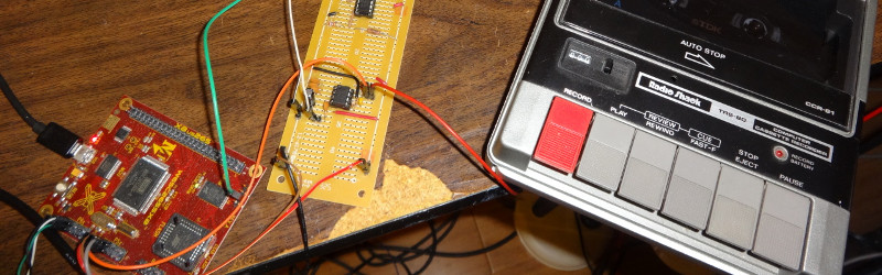
Before USB drives became pocket lint with a file system, before SD cards hid gigabytes under a fingernail, and before cloud storage started acting like a magical attic, home computers saved programs on ordinary audio cassette tapes. It sounds delightfully strange now: a computer would screech, chirp, and warble into a tape recorder, and those sounds were your software. Yet the idea was brilliant. Cassette recorders were cheap, common, reusable, and good enough to turn sound into data.
Making a cassette mass storage interface today is part electronics project, part retrocomputing archaeology, and part patience test. The basic goal is simple: convert digital data from a computer, microcontroller, or retro system into audio tones that can be recorded on tape, then later decode those tones back into data. The practical details are where the fun begins. You have to think about signal levels, modulation, noise, timing, headers, checksums, and the very real possibility that your tape deck has the personality of a sleepy raccoon.
This guide explains how a cassette storage interface works, what design choices matter, and how to build a practical system inspired by classic standards such as the Kansas City Standard, vintage home computer tape systems, and modern hobbyist projects using Arduino-style microcontrollers, Python-generated audio, comparators, filters, and simple decoding logic.
What Is a Cassette Mass Storage Interface?
A cassette mass storage interface is a bridge between digital electronics and analog audio tape. On one side, you have binary data: ones and zeros from a microcomputer, UART, microcontroller, or custom breadboard CPU. On the other side, you have an audio cassette recorder that only understands changing voltage as sound. The interface translates data into tones, sends those tones to the tape recorder, and later reads the tones back from the tape output.
The word “mass storage” is funny by modern standards. A cassette may store only kilobytes or a few megabytes depending on speed, encoding, and tape quality. But in the 1970s and early 1980s, that was enough to save BASIC programs, machine code, configuration files, games, and development tools. Compared with typing an entire program back in after every power cycle, cassette storage was not just convenient; it was a tiny miracle with a rewind button.
Why Cassette Storage Worked So Well for Early Computers
Early microcomputer users needed affordable storage. Paper tape was awkward, floppy drives were expensive, and hard drives were far beyond the average hobbyist budget. Cassette recorders, however, were already sitting in homes, schools, and electronics workbenches. They were designed for audio, but digital data could be represented as sound. Once that trick was understood, the humble tape deck became a low-cost data drive.
Classic systems used several methods, but many relied on frequency-shift keying, often shortened to FSK. In FSK, one frequency represents one binary value and another frequency represents the other. For example, a low tone might represent a zero, while a higher tone represents a one. The tape recorder does not need to know that it is storing computer data. It simply records the sound. The interface handles the meaning.
The Core Concept: Turning Bits Into Sound
Digital circuits usually work with clean voltage levels: high means one, low means zero. Audio cassette decks work with continuously changing analog signals. To store data on cassette, the interface must convert a stream of bits into an audio waveform. The most common options include FSK, phase-based encoding, Manchester encoding, and pulse-width methods.
Frequency-Shift Keying
FSK is historically popular because it is simple and robust. A decoder can detect whether the incoming audio is closer to one frequency or another. The Kansas City Standard, one of the most famous early cassette data standards, used audio tones around 1200 Hz and 2400 Hz. This worked with ordinary consumer cassette recorders and gave hobbyists a shared approach for data storage.
Manchester Encoding
Manchester encoding represents bits by transitions rather than only by tone. It can be easier to recover timing because every bit contains a predictable change. Modern hobbyist cassette projects sometimes use Manchester-style audio files generated by software, then record them to tape. This approach works well when a microcontroller or computer program handles the encoding and decoding.
Raw UART-to-Audio Methods
A simple UART-to-cassette interface can encode serial data into audio and decode it back into serial form. This is attractive because UART communication is familiar, widely supported, and easy to test with microcontrollers. However, raw serial waveforms should not usually be recorded directly as square waves without conditioning. Cassette decks prefer audio-like signals, and they may distort sharp edges, remove DC offsets, or alter low-frequency components.
Main Parts of a Cassette Storage Interface
A practical cassette mass storage interface has two halves: the record path and the playback path. The record path converts digital output into a safe audio signal for the cassette recorder. The playback path converts audio from the cassette deck back into logic-level data.
1. Digital Source
The digital source can be a retrocomputer, a 6502 breadboard computer, an Arduino, a Raspberry Pi Pico, an FPGA, or a modern PC producing audio files. For a simple project, a microcontroller is usually easiest because it can generate tones, time pulses, add checksums, and display debugging information.
2. Encoder
The encoder decides how ones and zeros become sound. In an FSK design, it generates one tone for zero and another tone for one. In a software-assisted system, a Python script or desktop utility may create a WAV file from binary data. That WAV file can then be played into a tape recorder or directly into a retrocomputer’s cassette input.
3. Output Level Control
Cassette microphone inputs and line inputs expect different signal levels. Too little signal causes unreliable reads. Too much signal causes clipping, distortion, and a waveform that looks like it lost a fight with a brick wall. A resistor divider, potentiometer, capacitor coupling, or simple amplifier stage can help set the correct level.
4. Tape Recorder
The recorder can be a vintage cassette deck, portable tape recorder, microcassette recorder, or even a digital audio recorder for testing. For real cassette work, a deck with a clean output, stable speed, and manual level control is ideal. Automatic gain control can sometimes help, but it can also damage consistency by changing levels during the recording.
5. Input Conditioning
Playback audio needs to be shaped before a digital circuit can understand it. This may involve filtering, amplification, rectification, zero-crossing detection, or a comparator. A Schmitt trigger can be useful because it cleans up noisy transitions and prevents the decoder from panicking every time the tape hisses.
6. Decoder
The decoder measures frequency, timing, or transitions and reconstructs the original data. A microcontroller can count zero crossings, measure pulse durations, or sample audio with an ADC. Older designs used analog filters, phase-locked loops, monostable circuits, or dedicated modem-style chips.
A Simple Architecture for Beginners
One beginner-friendly design is a microcontroller-based FSK cassette interface. The microcontroller receives bytes over serial, converts them into audio tones, and sends those tones through a capacitor and level-control resistor network to the cassette recorder. During playback, the tape output goes through an input protection resistor, coupling capacitor, bias network, and comparator or ADC input. The microcontroller then decodes the tones and reconstructs the bytes.
This architecture is flexible because most of the intelligence lives in software. You can adjust bit rate, tone frequencies, preamble length, checksum style, and error handling without rewiring half the circuit. It also gives you serial debugging, which is priceless. When the interface fails, and it will fail at least once, debugging messages can save you from blaming the cassette deck, the tape, the moon phase, and your own life choices.
Choosing a Data Format
A cassette storage system needs more than raw bytes. It needs structure. A reliable format usually includes a leader tone, synchronization pattern, file header, data blocks, checksums, and an end marker.
Leader Tone
The leader tone gives the playback circuit time to stabilize. It also helps the decoder detect that real data is coming. Many classic systems used several seconds of tone before the actual file began. This may feel slow, but it is extremely useful. Tape decks have motors, belts, heads, and analog circuits. They appreciate a polite warning before being asked to behave like a disk drive.
Sync Pattern
A sync pattern tells the decoder where the data starts. It should be something unlikely to appear accidentally in noise. A repeated byte pattern such as 0x55 can be useful because its alternating bits create a clear timing reference.
Header
The header can store the file name, file type, load address, length, version, or machine target. For a retrocomputer, this might include the memory address where the program should be loaded. For a general microcontroller system, it may simply contain the file size and a name.
Data Blocks
Breaking data into blocks makes error detection easier. Instead of recording one long stream and hoping for the best, each block can include its own number and checksum. If one block fails, the system can report exactly where the problem happened.
Checksum or CRC
A checksum is the minimum protection you should add. A cyclic redundancy check, or CRC, is better. Audio tape is noisy. Dropouts happen. Speed can drift. A checksum lets the decoder detect bad data instead of confidently loading nonsense into memory and then acting surprised when the program turns into digital soup.
Picking a Speed: Reliability Beats Bragging Rights
It is tempting to chase high baud rates. After all, nobody wants to wait five minutes for a tiny file. But cassette storage rewards patience. Lower speeds are more reliable because the tape system has more time to represent each bit clearly. Higher speeds demand better tape, cleaner heads, more stable transport, and more careful filtering.
A conservative starting point is around 300 baud, inspired by early standards. Once that works, you can experiment with 600, 1200, 2400, or higher. Some modern hobbyist projects have pushed cassette or microcassette storage faster, especially with microcontrollers and cleaner decoding. Still, the best speed is the one that loads correctly every time, not the one that looks heroic in a project log and fails whenever someone sneezes near the tape deck.
Recording Path Design
The recording path should create a clean, appropriately sized audio signal. A microcontroller output pin can generate a square wave, but a raw square wave contains many harmonics. Many cassette decks will record it, but filtering or shaping can improve results. A simple RC low-pass filter can soften the waveform. Capacitor coupling removes DC. A potentiometer lets you adjust level.
For a basic record circuit, the microcontroller tone output can pass through a resistor, then through a coupling capacitor into a potentiometer connected as a level control. The output goes to the cassette recorder’s microphone or line input. Keep levels modest. If the tape sounds harsh and visibly clips on an oscilloscope or audio editor, reduce the level.
Playback Path Design
The playback path is usually more sensitive than the record path. The cassette output may be weak, noisy, or uneven. The goal is to convert it into a clean signal for the decoder. One common method is to feed the audio into a comparator with hysteresis. Another is to sample the signal with a microcontroller ADC and decode it in software.
A comparator-based design is simple and fast. The audio is centered around a reference voltage, then the comparator switches high or low depending on whether the waveform is above or below that reference. Hysteresis helps prevent rapid false switching from tape hiss. An ADC-based design is more flexible because software can estimate amplitude, detect frequency, and adapt thresholds, but it requires more processing.
Software: The Secret Sauce
Software makes a cassette interface far more forgiving. During recording, the encoder can add silence, leader tones, headers, block numbers, and checksums. During playback, the decoder can measure timing, reject impossible transitions, resynchronize after small errors, and display useful diagnostics.
A good test workflow is to begin without tape. Generate audio from the encoder and feed it directly into the decoder. If that works, record to a digital audio file and play it back. If that works, move to cassette. This staged approach prevents you from trying to debug software, analog electronics, tape alignment, and 40-year-old rubber belts all at once. That way lies madness, or at least a very messy desk.
Testing the Interface
Start with a short file, such as a few bytes of text. Record it. Play it back. Compare the decoded data with the original. Then increase the file size. Test different volume settings. Try both sides of the tape. Try a new cassette and an old cassette. Try recording with noise reduction off. Keep notes, because cassette behavior can change dramatically with small adjustments.
An oscilloscope is helpful, but not mandatory. A computer audio editor can also show the waveform. Look for clipping, dropouts, unstable levels, and sudden changes. If the waveform is too tiny, increase record volume. If it is flattened at the top and bottom, reduce volume. If the decoded data fails after the first few seconds, add a longer leader or improve synchronization.
Common Problems and Fixes
The Decoder Sees Nothing
Check the playback volume, cable wiring, ground connection, and input bias. Make sure the cassette output is actually producing audio. Test with headphones first. If you cannot hear the data tones, the circuit cannot decode them either.
The Signal Clips
Lower the record level. Clipping destroys frequency information and makes decoding unreliable. A slightly quieter clean signal is better than a loud distorted one.
Data Works Directly but Fails on Tape
This usually means the audio path is changing the signal too much. Slow down the baud rate, use more robust encoding, add a longer leader, improve filtering, or adjust levels.
Long Files Fail but Short Files Work
Add block-level checksums and improve timing recovery. Tape speed drift accumulates over time. A decoder that resynchronizes often will handle long files better than one that assumes perfect timing forever.
Modern Enhancements for a Retro Idea
You do not have to build the entire system exactly like it was 1981. Modern tools make cassette storage more enjoyable. A Python script can convert binary files into WAV files. A microcontroller can display status on an OLED screen. A PC can analyze recorded audio and show where decoding failed. An SD card can even store cassette images while the interface outputs authentic audio to a retro machine.
You can also build a hybrid interface that supports real cassettes and digital audio files. Many retrocomputer users now load programs from phones, laptops, or dedicated audio players through the cassette input. The same encoder that records to tape can often create files for these devices. That gives you the charm of cassette storage without requiring every test to involve rewinding plastic ribbon like a tiny analog time machine.
Safety and Practical Build Tips
Keep the project low voltage. Use battery-powered or USB-powered circuits where possible. Do not open mains-powered tape decks unless you are trained to work safely around hazardous voltages. Use coupling capacitors to avoid feeding DC into audio equipment. Add resistors to protect microcontroller pins. Label your cables. Cassette projects already have enough ways to confuse you; mystery wires should not be one of them.
Use shielded audio cables if the signal is noisy. Clean the tape heads. Avoid damaged tapes. Turn off aggressive audio processing. If the deck has manual record level control, use it. If it has automatic gain control, test carefully because it may change the level during the leader tone and affect decoding.
Real-World Example: A Minimal FSK Cassette Interface
Imagine a small interface built around a microcontroller. The encoder sends a 2400 Hz tone for a one and a 1200 Hz tone for a zero. Before data begins, it plays a five-second leader tone. Then it sends a sync pattern, a file header, and data blocks. Each block ends with a CRC. The output passes through a resistor, capacitor, and potentiometer into the cassette recorder.
On playback, the cassette output goes through a capacitor into a biased comparator input. The microcontroller measures the time between transitions to estimate frequency. If it sees a pattern matching the leader and sync bytes, it starts decoding blocks. When a block passes its CRC, it stores or sends the recovered bytes. If the CRC fails, it reports the block number and waits for another attempt.
This is not the only way to build the system, but it captures the core idea. The magic is not in expensive parts. It is in choosing a forgiving encoding, controlling audio levels, and giving the decoder enough structure to recognize valid data.
Extra Experience Notes: Lessons From Building and Using a Cassette Mass Storage Interface
The first lesson is that cassette storage is less about perfection and more about negotiation. You are negotiating with analog tape, motor speed, head alignment, noise, cable quality, and signal levels. Digital storage usually feels strict: the file is there or it is not. Cassette storage feels more like tuning a radio station. When everything lines up, the data appears. When one thing drifts, the computer stares back as if you just fed it soup through the keyboard.
One of the most useful habits is to test in layers. Do not begin by recording a full program to a questionable cassette and then wondering why it fails. First, confirm the encoder produces the right audio. Then loop the audio directly into the decoder. Then record digitally and decode the recording. Only after that should you involve real tape. This method makes troubleshooting calmer because each stage proves one part of the system.
Volume setting is another surprisingly important experience. Beginners often assume louder is better. With cassette data, louder can be worse. If the signal overloads the recorder input, the waveform clips. The tones may still sound strong to your ears, but the decoder may struggle because the frequency information has been damaged. A clean medium-level signal usually beats a loud crunchy one. The best setting is often just below visible distortion.
Leader tones are boring until you remove them. Then they become obviously necessary. A leader gives the tape transport time to stabilize and gives the decoder time to lock onto the signal. In practice, a few extra seconds of leader can improve reliability more than a complicated circuit change. It feels inefficient, but cassette storage was never trying to win a drag race against an SSD.
Block design also matters. Saving data as one long uninterrupted stream is simple, but it is fragile. Blocks with checksums make the system feel more professional. They also make debugging much easier. Instead of knowing only that “the load failed,” you can learn that block 12 failed, which may point to a dropout, a bad section of tape, or a timing problem after several seconds of playback.
Another practical discovery is that different tape machines behave differently. A full-size cassette deck may outperform a tiny portable recorder. A machine with manual level control may be easier to tune than one with automatic gain. Old belts can cause speed instability. Dirty heads can weaken high frequencies. Even the cable can matter if it introduces hum or poor grounding. The storage interface may be perfectly fine while the tape deck quietly causes chaos in the background.
Modern software tools make the project much less mysterious. Recording the cassette output into a computer and viewing the waveform can reveal clipping, dropouts, and level changes. Frequency analysis can show whether your two tones are clear. A script can compare decoded bytes with the original file and report exact error positions. These tools let you combine retro charm with modern convenience, which is the best kind of technological cheating.
Finally, the project teaches respect for early computer users. Loading software from cassette was slow, noisy, and sometimes unreliable, but it was also affordable and clever. Making your own cassette mass storage interface shows how much engineering can happen with simple parts and smart encoding. It turns sound into memory, and it reminds us that data storage does not have to look modern to be ingenious.
Conclusion
Making a cassette mass storage interface is a rewarding retrocomputing project because it connects digital logic with the wonderfully imperfect world of analog audio. The core idea is simple: encode bits as sound, record them to cassette, and decode them later. The best results come from careful choices: a reliable modulation scheme, clean signal levels, a useful file format, leader tones, synchronization, and error checking.
Whether you are building storage for a breadboard computer, experimenting with Arduino and audio tape, restoring a vintage machine, or simply exploring how early personal computers saved data, cassette storage offers a hands-on lesson in practical engineering. It is slow, charming, occasionally stubborn, and deeply satisfying when a program loads successfully from a strip of magnetic tape.