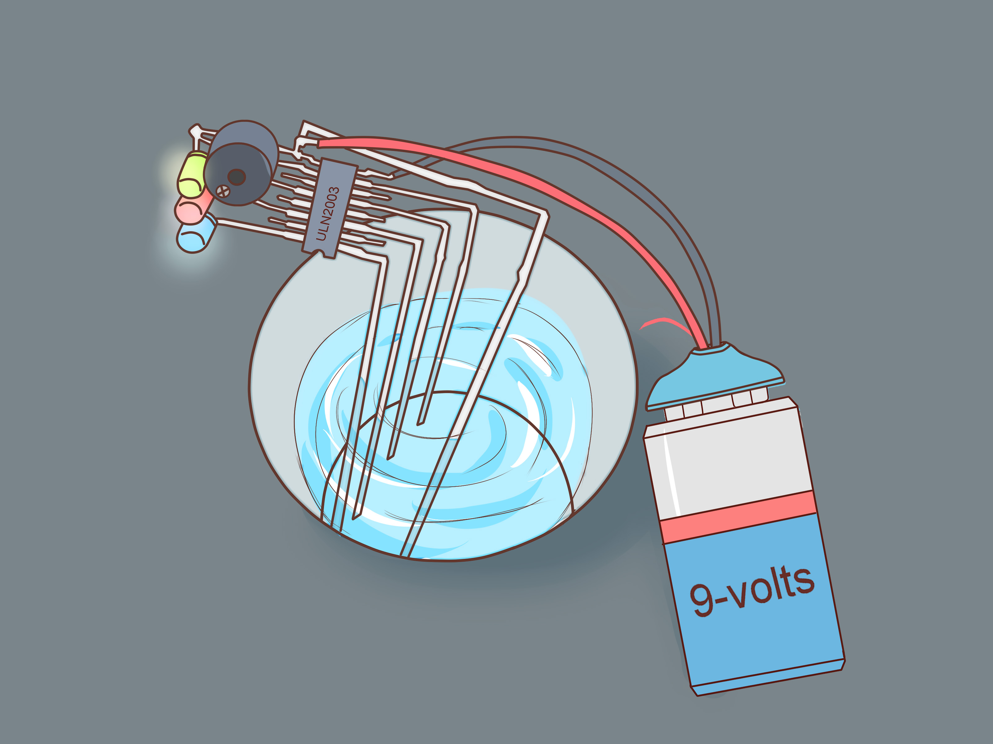
A water level indicator is one of those small DIY electronics projects that feels surprisingly powerful. One minute you are staring at a tank, bucket, aquarium, or rain barrel like a person waiting for toast to pop up. The next minute, your homemade circuit is politely telling you, “Relax, the water is here.” That is progress. That is civilization. That is also much better than accidentally overflowing a container and creating an indoor pond nobody asked for.
In this guide, you will learn how to make a simple water level indicator in 12 clear steps using beginner-friendly parts such as wires, LEDs, resistors, a buzzer, and a low-voltage power source. We will also discuss Arduino water level indicator options, contactless ultrasonic sensing, float switches, troubleshooting tips, and real-world experience from building and testing these devices. The goal is not just to make something that lights up; the goal is to understand why it works, how to improve it, and how to keep it safe.
Important safety note: This project is designed for low-voltage DC power only, such as a battery pack or USB-powered microcontroller. Do not connect homemade water sensor probes directly to household AC power, pumps, outlets, or mains wiring. Water and high voltage are not a buddy comedy. Keep the electronics dry, insulated, and away from splashes.
What Is a Water Level Indicator?
A water level indicator is a simple device that shows how much water is inside a container. It may use LEDs, a buzzer, a display, or even a microcontroller to alert you when water reaches a certain height. Basic models use conductive probes: when water touches two wires, it completes a tiny low-voltage circuit. More advanced versions use analog sensors, float switches, capacitive sensors, pressure sensors, or ultrasonic modules that measure distance from the top of the tank to the water surface.
For a beginner project, a probe-based indicator is affordable and easy to understand. Water conducts electricity because of minerals and dissolved ions, so when a probe at a certain height touches the water, it can trigger an LED or buzzer. Pure distilled water conducts poorly, but tap water usually works well enough for a simple indicator. If your circuit acts shy, the water may simply be too clean. Apparently even water can be an overachiever.
Materials and Tools You Need
Before building the circuit, gather your parts. You can make a basic water level indicator with common electronics components. For a simple three-level version, prepare:
- 1 small breadboard or perfboard
- 3 LEDs in different colors, such as green, yellow, and red
- 3 resistors for the LEDs, usually 220 ohms to 1 kilo-ohm
- 3 NPN transistors such as BC547, 2N2222, or similar small-signal transistors
- 3 base resistors, commonly 10 kilo-ohms
- 1 active buzzer for the “full” level alert
- Insulated hookup wire
- 4 stainless steel probes, screws, or stripped wire ends
- 1 low-voltage DC supply, such as a 5V battery pack
- Electrical tape, heat-shrink tubing, or waterproof enclosure materials
- A plastic bottle, cup, or small tank for testing
You can also build an Arduino water level indicator using a water level sensor module connected to an analog input pin. That version is helpful when you want readings on a serial monitor, LCD, or IoT dashboard. However, the transistor-and-LED version is perfect for learning the basic idea first.
How to Make a Water Level Indicator: 12 Steps
Step 1: Decide What Levels You Want to Measure
Choose the number of water levels you want to detect. A simple build might show three levels: low, medium, and full. A more detailed tank monitor could show empty, quarter, half, three-quarter, and full. For this guide, we will use three LEDs and one buzzer. The green LED means the tank has reached the lower level, the yellow LED means the middle level, and the red LED plus buzzer means the tank is full.
Keep the design practical. If you are monitoring a small container, three levels may be enough. If you are monitoring a tall water tank, more probes give better information. Do not worry about making it NASA-level accurate on the first attempt. NASA probably also started with someone saying, “What if we add one more wire?”
Step 2: Understand the Common Probe
A basic water level indicator needs one common probe placed near the bottom of the tank. This common probe connects to the positive side of the low-voltage sensing path or to the circuit reference, depending on your design. Each level probe sits at a different height. When water rises and touches both the common probe and a level probe, a small current can flow through the water and activate that stage of the circuit.
The common probe should extend lower than the others so it remains in contact with the water once filling begins. If the common probe is too high, the indicator will not work until the water reaches that point, which is like hiring a security guard who only shows up after the party is over.
Step 3: Prepare the Probes
Use stainless steel screws, stainless wire, or corrosion-resistant metal for the probes. Copper wire works for a quick classroom demonstration, but it corrodes faster when used in water for long periods. Strip the ends of the wires only where they need to contact the water. Leave the rest insulated so the probes do not accidentally touch one another.
Mount the probes vertically inside the container. Place the common probe at the bottom and the three level probes at low, medium, and full heights. Keep the probes separated by a small gap. They should not touch directly, because direct contact would trigger the circuit even without water. In electronics, accidental touching is not romance; it is a short circuit.
Step 4: Build the LED Indicator Stages
Each LED stage works like a tiny switch. The water completes a weak connection between the common probe and the level probe. That signal goes through a resistor to the base of an NPN transistor. When the transistor turns on, current flows through an LED and its resistor, making the LED light up.
For each stage, connect the LED and resistor in series with the transistor collector path. The emitter goes to ground. The base connects through a resistor to its level probe. This base resistor is important because it limits current and protects the transistor. Skipping it may still work briefly, but it is bad design, a little like building a chair and deciding legs are optional.
Step 5: Add the Buzzer for the Full Level
The buzzer should activate only when the top probe touches the water. Connect the buzzer to the output of the full-level transistor stage. If you are using a small active buzzer rated for your supply voltage, it can usually be driven by a transistor. Always check the buzzer voltage and current rating before connecting it.
An active buzzer is easier for beginners because it makes sound when powered. A passive buzzer needs a pulsing signal, usually from a microcontroller. For a no-code project, choose an active buzzer. Your future self will thank you, and your breadboard will have fewer reasons to look haunted.
Step 6: Connect the Low-Voltage Power Supply
Use a safe low-voltage DC power source. A 5V battery pack, 9V battery with proper resistor values, or USB power bank can work for a small indicator. Keep the power supply outside the water container and away from splashes. If the project will be used near a real tank, place the circuit inside a plastic enclosure and route only the insulated probe wires into the tank.
Do not power this homemade circuit directly from a wall outlet. Do not attach it to a mains-powered pump unless you are using properly rated, enclosed, certified control hardware and qualified help. A water level indicator should prevent problems, not audition for a disaster movie.
Step 7: Test One Level at a Time
Before filling the container fully, test each level with a small amount of water. Touch the common probe and the low-level probe with a wet finger or a damp cloth to see whether the green LED lights up. Then test the medium and full probes. If one LED does not light, check the LED polarity, resistor placement, transistor pins, and wire connections.
LEDs have polarity. The longer leg is usually the positive side, while the shorter leg usually goes toward ground through the transistor path. Transistors also have specific pin orders, and different models may arrange emitter, base, and collector differently. Always check the datasheet or package information for your exact transistor.
Step 8: Fill the Container Slowly
Now test the indicator in a realistic way. Slowly add water to the container and watch the LEDs. The first LED should turn on when the water reaches the low probe. The second LED should turn on at the medium probe. The third LED and buzzer should activate when the water reaches the top probe.
If the LEDs flicker, the probes may be dirty, too far apart, or unstable. Moving water can also cause a flickering signal. You can reduce this by securing the probes firmly, using slightly larger metal contact areas, or adding small filtering components in more advanced versions. For a simple build, stable probe placement solves many problems.
Step 9: Label the Levels
After confirming that the circuit works, label the indicator. Mark the LEDs as Low, Medium, and Full. If the indicator will be used by someone else, make the labels obvious. A water tank monitor should not require decoding like an ancient treasure map.
You can also mark the container itself with matching level lines. This makes calibration easier and helps you verify that the probes are positioned correctly. If your red LED turns on before the water is actually full, move the top probe higher. If the buzzer sounds too late, move the probe lower.
Step 10: Waterproof and Protect the Circuit
The probes belong near water; the electronics do not. Put the breadboard or finished circuit in a dry enclosure. Use cable glands, silicone sealant, or heat-shrink tubing where wires enter the box. Keep the power switch and battery compartment easy to reach but protected from moisture.
If the circuit will be used outdoors, protect it from rain, insects, dust, and direct sunlight. A plastic project box with a gasket is useful. Do not seal everything so tightly that condensation becomes trapped inside. Moisture has a talent for finding electronics, usually right after you say, “It should be fine.”
Step 11: Improve the Design with Arduino
Once the basic version works, you can upgrade it with Arduino. A water level sensor module can send an analog signal to an Arduino analog input. The Arduino reads the value, compares it to thresholds, and turns LEDs or a buzzer on or off. This gives you more control than a basic transistor circuit.
For example, you can program the Arduino to show four levels: empty, low, medium, and full. You can also add an LCD display, data logging, Wi-Fi alerts, or a delay so the buzzer does not scream every time the water wiggles. Analog sensors should be calibrated by recording readings when the sensor is dry, partly submerged, and fully submerged. Calibration turns random numbers into useful information, which is also a good life goal.
Step 12: Maintain and Recalibrate the Indicator
Water level indicators need occasional maintenance. Mineral buildup, algae, rust, and loose wires can affect performance. Clean the probes every few weeks if the system is used regularly. Inspect the wires for cracks or corrosion. Replace batteries before they become weak enough to make the circuit behave like it needs coffee.
If you use an analog sensor, recalibrate it after changing containers, water type, sensor position, or power source. Tap water, rainwater, and filtered water may produce different readings. For long-term projects, consider a float switch or ultrasonic sensor, which can reduce corrosion issues because they do not rely on exposed conductive probes in the same way.
Choosing the Right Water Level Sensor
Conductive Probe Sensor
This is the simplest method and the main focus of this guide. It is cheap, easy to build, and excellent for learning. The downside is corrosion and sensitivity to water conductivity. It is best for demonstrations, small tanks, and non-critical applications.
Float Switch
A float switch uses a floating part that rises or falls with the water. When the float reaches a set point, it opens or closes a switch. Float switches are reliable for simple “too low” or “too full” alerts. They are not ideal when you need continuous measurement, but they are great for clear yes-or-no detection.
Ultrasonic Sensor
An ultrasonic water level indicator measures distance from the sensor to the water surface. The sensor is mounted above the water, so it does not touch the liquid. This makes it useful for tanks where corrosion is a concern. However, foam, steam, uneven surfaces, and narrow tank shapes can affect readings.
Capacitive Sensor
A capacitive sensor detects changes in capacitance caused by nearby water. Some capacitive designs can work through a plastic container wall, which is wonderfully neat when you do not want holes in the tank. Capacitive sensors need calibration and may behave differently with different container materials and wall thicknesses.
Common Problems and Easy Fixes
The LED Does Not Turn On
Check the LED direction, transistor pinout, resistor values, and power supply. Also verify that the common probe is actually touching the water. If the container has very clean water, add a tiny pinch of salt only for testing in a non-drinking-water container. Do not do this in aquariums, drinking water, or plant systems unless you know it is safe for that use.
The Buzzer Never Stops
The top probe may be touching another probe or a wet surface. Dry the outside of the container, separate the wires, and inspect the breadboard for accidental connections. Water droplets can bridge contacts and create false alarms.
The Readings Are Unstable
Unstable readings usually come from loose probes, moving water, weak batteries, or noisy connections. Secure the probes, shorten long wires, and keep signal wires away from motors or pumps. With Arduino, you can average several readings to smooth the output.
The Probes Corrode Quickly
Corrosion happens faster with exposed metal and continuous DC current. Use stainless steel probes, reduce the sensing current, or power the sensor only when taking a reading. For a more durable system, use a float, capacitive, or ultrasonic sensor.
Practical Uses for a DIY Water Level Indicator
A homemade water level indicator can be useful in many small projects. You can use it to monitor a rain barrel, prevent a small tank from overflowing, check a plant-watering reservoir, track aquarium refill levels, or create a science fair demonstration. It is also a great introduction to sensors, transistors, circuits, and microcontrollers.
The project teaches several core electronics ideas at once: conductivity, switching, polarity, resistance, calibration, and signal detection. That is a lot of learning from a few wires and a cup of water. Not bad for something that costs less than a fancy sandwich.
Experience Notes: What Building a Water Level Indicator Teaches You
The first time you build a water level indicator, the project may look almost too simple. A few wires go into a container, some LEDs sit on a breadboard, and suddenly you have a tiny control panel that reacts to rising water. But the real learning starts when the circuit does not behave perfectly. Maybe the green LED works, the yellow LED refuses to cooperate, and the buzzer acts like it has joined a marching band. That is normal. In fact, troubleshooting is where the project becomes genuinely valuable.
One of the biggest lessons is that water is not always electrically predictable. Tap water in one home may trigger the circuit easily, while filtered water may produce a weaker response. If you test the same project in rainwater, aquarium water, and bottled water, you may get different behavior. This teaches a practical point: sensors do not measure the idea of “water” in some magical way. They measure a physical property, such as conductivity, distance, pressure, or capacitance. Understanding that makes you much better at designing and fixing real systems.
Another useful experience is learning how important mechanical placement is. Many beginners focus only on the circuit diagram, but the probe layout matters just as much. If probes are too close, water droplets can bridge them. If they are too far apart, weakly conductive water may not trigger the transistor reliably. If the wires are loose, the indicator flickers when the container moves. A good water level indicator is part electronics project and part tiny construction project. The circuit may be smart, but the wires still need to stand where you put them.
You also learn why “temporary” breadboard projects should not become permanent tank monitors without protection. Breadboards are great for testing, but they are not waterproof, rugged, or meant for damp environments. After the prototype works, the better move is to transfer the design to perfboard or a small PCB, mount it in an enclosure, and strain-relieve the wires. This prevents loose connections and makes the project safer. It also makes the finished device look less like a bowl of electronic spaghetti.
Calibration is another experience that separates a quick demo from a useful tool. When using Arduino, raw analog readings are only numbers until you connect them to real water heights. Fill the container in stages, write down the readings, and set thresholds based on your actual test results. Do not simply copy someone else’s threshold values and expect perfection. Their sensor, water, power supply, and container are probably different. Electronics tutorials are excellent maps, but your own measurements are the road signs.
Finally, this project teaches design restraint. It is tempting to add Wi-Fi, a display, a pump controller, a cloud dashboard, and maybe a dramatic theme song. Start simple. Make the LEDs work first. Add the buzzer next. Then consider Arduino or a contactless ultrasonic sensor. Building in stages makes mistakes easier to find and success easier to enjoy. A reliable simple water level indicator is better than a complicated one that only works when Mercury is in retrograde.
Conclusion
Learning how to make a water level indicator is a practical and rewarding electronics project. With a few low-voltage components, you can build a simple system that shows when a container reaches low, medium, and full levels. The basic probe method teaches conductivity and transistor switching, while Arduino, float switches, capacitive sensors, and ultrasonic modules give you paths for future upgrades.
The key is to build safely, test slowly, and protect the electronics from moisture. Use low-voltage DC power, keep the circuit dry, and never connect a homemade water sensor directly to household electricity. Once your indicator works, you can improve it with cleaner wiring, better probes, calibration, a display, or contactless sensing. In the end, you get more than a blinking LED. You get a useful device, a better understanding of sensors, and the quiet satisfaction of stopping water before it turns your floor into a surprise swimming pool.