Note: This article is for educational and amateur-radio discussion only. Transmitting on the 6 meter ham band requires the proper amateur radio license, clean equipment, and compliance with FCC rules. Do not modify or operate CB equipment illegally on CB channels, and do not transmit any homebuilt or converted radio until it has been tested into a dummy load and verified for frequency accuracy, power level, and spurious emissions.
Introduction: When 1970s Road Chatter Meets Microcontroller Mischief
There is something wonderfully odd about the phrase “CB Radio + Arduino = 6 Meter Ham Band.” It sounds like a garage experiment, a ham shack dare, and a math problem written by someone who stores coax cable in coffee cans. But behind the playful equation is a real and fascinating idea: taking the bones of an old 27 MHz CB radio, adding modern digital frequency control with an Arduino, and using that platform as part of a conversion or transverter system for the 6 meter amateur radio band.
CB radio and the 6 meter ham band live in different neighborhoods. CB radio operates around 27 MHz, often called the 11 meter band, while 6 meters sits at 50 to 54 MHz in the United States. That means you are not simply turning a knob and magically hopping from truck-stop channel 19 to the “Magic Band.” A proper project requires frequency conversion, filtering, oscillator control, alignment, and, above all, respect for the rules. In other words, this is not a screwdriver-and-prayer modification. It is a real RF project.
The reason hobbyists care is simple: old CB radios are plentiful, inexpensive, and often built with analog stages that can be studied, repaired, and repurposed. Arduino boards and small clock-generator modules, especially Si5351-based boards, make it easier than ever to build a digital VFO, control an oscillator, drive a display, switch bands, and create a more civilized user interface than “guess where the crystal went.” Combine the two thoughtfully, and you get a project that teaches radio theory, microcontroller programming, frequency synthesis, and 6 meter operating habits all at once.
What the Project Really Means
The title does not mean every CB radio can be turned into a legal 6 meter transceiver by soldering an Arduino to the volume knob. The smarter interpretation is this: an old CB radio can become a useful platform, driver, IF strip, audio chain, or experimental chassis, while the Arduino handles digital frequency control, display logic, and switching. In many builds, the missing bridge between 27 MHz and 50 MHz is a transverter, a circuit that converts signals from one frequency range to another.
A practical example looks like this. A CB transceiver produces or receives a signal around 27 MHz. A local oscillator, controlled by an Arduino-driven synthesizer, mixes that signal with another frequency to produce output in the 50 MHz region. If the math is arranged correctly, the result can fall inside the 6 meter ham band. Filters then remove unwanted mixer products, and amplifiers bring the signal to a useful but legal level. The receiver path works in reverse: a 50 MHz signal enters through a 6 meter antenna, is filtered, mixed down, and processed by the radio’s existing receiver stages.
That sounds simple until the RF gremlins arrive wearing tiny lab coats. Mixers create more than one signal. Oscillators drift. Old CB radios may have narrow channelized designs. Transmitters can produce harmonics. Receivers can overload. Antennas that work on 27 MHz are not automatically happy at 50 MHz. This is why successful conversions rely on measurement, filtering, shielding, and patience. A frequency counter, dummy load, oscilloscope, wattmeter, and preferably a spectrum analyzer are not fancy luxuries here. They are the adult supervision.
CB Radio Basics: The 27 MHz Starting Point
In the United States, Citizens Band radio is a personal radio service with 40 shared channels between 26.965 MHz and 27.405 MHz. CB is designed for short-range personal, business, traveler, and emergency communications. It does not require an individual amateur radio license, but it does require type-certified equipment and rule-compliant operation. Power is limited, channel frequencies are fixed, and the service is not meant to become a playground for experimental transmitters.
This distinction matters. Once a CB radio is modified to transmit outside its certified CB channels, it is no longer a compliant CB transmitter for CB operation. In amateur radio, licensed operators are allowed much more technical freedom, including homebuilt and modified equipment, but that freedom belongs inside the amateur service and comes with responsibility. The operator must ensure the station operates on authorized frequencies, uses acceptable emissions, identifies properly, and does not cause harmful interference.
For the builder, CB equipment is attractive because it is inexpensive and educational. Many older units use discrete RF sections, ceramic filters, IF transformers, and analog audio stages that are easier to understand than modern surface-mount mystery boxes. A single-sideband CB radio is especially interesting because SSB is useful on 6 meters around the weak-signal portions of the band. AM-only sets can still teach plenty, but they are less flexible for serious 6 meter work.
Why 6 Meters Is Called the Magic Band
The 6 meter ham band covers 50 to 54 MHz in the United States. It sits at the borderland between HF behavior and VHF behavior, which is exactly why operators love it. Some days it behaves like a polite local VHF band: line-of-sight contacts, repeaters, modest antennas, and predictable coverage. Then, without asking permission, it opens through Sporadic-E propagation and suddenly a small station can work hundreds or even thousands of miles. The band can go from “nothing but receiver hiss” to “everyone is calling at once” faster than a cat can knock a solder spool off the bench.
Common 6 meter activities include SSB voice, CW, FM simplex, repeaters, digital modes, beacons, contesting, and DX chasing. The ARRL band plan places weak-signal activity in the lower part of the band, including the well-known 50.125 MHz SSB calling frequency. FM simplex and repeaters live higher in the band. A converted CB-style project is usually most interesting for SSB or AM experimentation, although clean FM work is possible with the right design.
Another reason 6 meters is friendly to homebrewers is antenna size. A half-wave dipole for 6 meters is roughly nine to ten feet overall, depending on construction and tuning. That is backyard-friendly, attic-friendly, and significantly easier than trying to hide a full-size 80 meter antenna from a homeowners association that already has opinions about your mailbox color. A small dipole, Moxon, vertical, or lightweight Yagi can provide real results when the band opens.
Where the Arduino Fits
The Arduino does not magically make RF cleaner, stronger, or legal. What it does beautifully is control things. In a CB-to-6-meter project, an Arduino can manage a programmable oscillator, display the operating frequency, apply an IF offset, read a rotary encoder, switch filters, control transmit/receive logic, store memories, and even handle calibration menus. It turns a pile of analog radio parts into something that feels intentional.
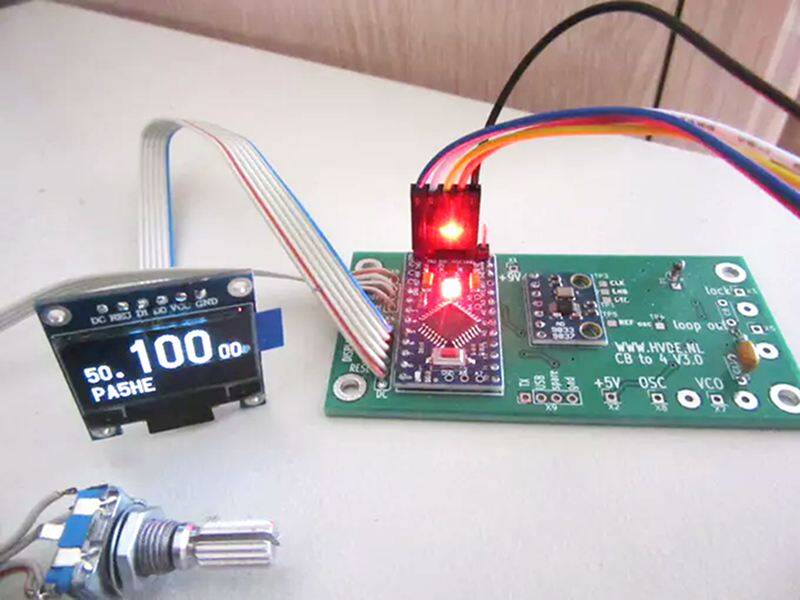
The most common companion is a clock-generator module such as the Si5351. This small chip can generate programmable clock outputs using internal PLLs and dividers. Controlled over I2C, it pairs naturally with Arduino boards. A typical builder might use an Arduino Nano, an Si5351 breakout, a small OLED display, a rotary encoder, push buttons, and a few switching transistors or relays. The Arduino code can be written to show the actual 6 meter frequency rather than the lower IF or driver frequency, which makes the converted rig much more pleasant to operate.
For example, suppose your system uses a 23 MHz oscillator to translate a 27 MHz signal upward into the 50 MHz range. The Arduino can be programmed so the display reads “50.125 MHz” even though part of the radio is still operating near its original CB-derived frequency. Better yet, it can apply offsets automatically, so tuning feels like a real 6 meter radio instead of a math quiz with RF leakage.
Conversion vs. Transverter: Choose Your Adventure
Direct Conversion of a CB Radio
A direct conversion attempts to modify the CB radio’s oscillator, tuned circuits, receiver front end, transmitter chain, and filtering so the unit operates directly on 50 MHz. This is ambitious. Many CB radios were designed around 27 MHz crystals, PLL chips, coils, and output transistors that are not automatically suitable for 50 MHz. You may need to replace or retune coils, redesign the VCO range, modify low-pass filters, and ensure the final amplifier behaves properly at VHF.
The advantage is elegance: one radio, one band, fewer external boxes. The disadvantage is that you may spend several evenings discovering that a component perfectly happy at 27 MHz becomes a tiny space heater at 50 MHz. Direct conversion is best for experienced builders with documentation, test gear, and a willingness to reverse-engineer the radio.
Using a CB Radio as a Driver for a 6 Meter Transverter
A transverter approach is often more realistic. Here, the CB radio remains closer to its original operating range, while an external converter shifts the signal to and from 6 meters. The Arduino-controlled oscillator provides the frequency translation, and the transverter includes band-pass filters, mixer stages, T/R switching, and gain control.
This approach also makes alignment more manageable. You can test the CB-derived driver separately, then test the oscillator, then test the receive converter, then test the transmit chain into a dummy load. Each stage can be verified before the full system is connected to an antenna. When something goes wrong, you are debugging a section instead of interrogating the entire radio like it owes you money.
Important Legal and Technical Boundaries
The legal boundary is straightforward: CB rules are for CB equipment on CB frequencies, while 6 meter operation belongs to licensed amateur radio. A modified CB radio should not be used as a CB transmitter unless it still complies with CB certification and operating rules. On the amateur side, the operator is responsible for the transmitted signal. That includes frequency accuracy, occupied bandwidth, spurious emissions, harmonic suppression, station identification, and staying within authorized band segments.
The technical boundary is equally important. A 27 MHz transmitter can produce harmonics, and the second harmonic of 27 MHz lands near 54 MHz, right around the upper edge of the 6 meter band. That does not mean a CB transmitter is “almost a 6 meter rig.” It means careless filtering can create trouble. A proper 6 meter project must include suitable band-pass and low-pass filtering so the intended signal is clean and unwanted products are suppressed.
Builders should also be cautious with power. Start small. Milliwatts and dummy loads are your friends. A low-power signal that is clean can be amplified later. A dirty signal amplified early is just a louder mistake. Think of RF power like hot sauce: a little can be useful, but dumping the bottle into everything does not make you a chef.
Parts and Tools That Make the Project Practical
A realistic project begins with the right parts. A stable Arduino-compatible board can handle control logic. An Si5351 module can serve as the programmable local oscillator. A rotary encoder gives smooth tuning. An OLED or LCD display shows frequency, mode, offset, and memory status. Relays or RF switches can manage transmit/receive paths. Mixers, filters, attenuators, and buffer amplifiers form the RF heart of the project.
On the test bench, you need more than enthusiasm. A dummy load rated for the expected power level is essential. A frequency counter or calibrated receiver helps confirm oscillator accuracy. A wattmeter shows output power. An oscilloscope helps with audio, control signals, and some RF troubleshooting. A spectrum analyzer or SDR-based spectrum display is extremely useful for spotting spurious outputs and harmonics. Even a modest SDR receiver can be a valuable “sanity check” when used carefully and not overloaded.
Documentation is another tool. Find the service manual for the CB radio if possible. Identify the PLL, IF frequency, mixer stages, filters, driver transistor, final transistor, and transmit/receive switching. Draw your own block diagram before touching the soldering iron. The moment you understand the signal path, the project changes from “poke and hope” to engineering.
A Practical Build Strategy
Step 1: Study the Donor Radio
Begin by identifying whether the radio is AM-only, AM/FM, or SSB-capable. For 6 meter weak-signal work, SSB is the most attractive. Confirm the radio works normally before modification. A broken radio is a poor donor unless your goal is to collect symptoms like trading cards.
Step 2: Define the Frequency Plan
Decide how the 27 MHz signal will translate to 50 MHz. Choose an oscillator frequency that creates the desired 6 meter output while keeping images and unwanted products manageable. This is where the Arduino and Si5351 shine: the software can calculate offsets and show the actual operating frequency.
Step 3: Build the Oscillator and Display
Prototype the Arduino, Si5351, encoder, and display on the bench. Confirm the oscillator output with a frequency counter or receiver. Add calibration correction if needed. Keep leads short, use decoupling capacitors, and shield the oscillator section if it will live near sensitive RF stages.
Step 4: Add Mixing and Filtering
Use a suitable mixer and filters to shift the signal. The filters are not optional decorations; they are what make the difference between a usable transverter and a tiny interference festival. Use band-pass filtering around 50 to 54 MHz and appropriate low-pass filtering after amplification.
Step 5: Test Receive First
Receive testing is safer and less dramatic than transmit testing. Use a signal generator, a nearby low-power source, or a known 6 meter beacon where available. Confirm sensitivity, tuning direction, stability, and image rejection. If the receiver cannot hear properly, the transmitter is not ready for prime time.
Step 6: Test Transmit Into a Dummy Load
When the transmitter path is ready, use a dummy load. Verify output frequency, power, modulation quality, and spectral cleanliness. Do not connect an antenna until the signal is known to be clean. This is where responsible homebrewing earns its badge.
Operating on 6 Meters After the Build
Once the project is aligned and legal, operating style matters. If using SSB, monitor 50.125 MHz for activity, but move away from the calling frequency once a contact is established. Check the lower part of the band for beacons. During summer Sporadic-E season, listen often. Openings can be brief, intense, and wildly fun.
For antennas, start simple. A dipole cut for 6 meters is cheap and effective. A small Moxon or three-element Yagi adds directionality without requiring a tower that looks like it belongs to a television station. Keep feed lines short and use coax suitable for VHF. Loss matters more at 50 MHz than it does at 27 MHz, so that mystery cable from the junk drawer may not be the hero of this story.
Digital tools can also help. Many operators watch online spotting networks, beacon lists, and propagation maps to see when the band is opening. Even if your converted rig is voice-only, these tools can tell you when to turn the dial and listen. The Magic Band rewards patience, timing, and the ability to stop mowing the lawn the moment the receiver comes alive.
Common Mistakes to Avoid
The first mistake is assuming frequency conversion is only about the desired output. Mixers produce sums, differences, oscillator leakage, and other unwanted products. Design filters before you design the front panel. A beautiful display cannot rescue a dirty RF chain.
The second mistake is ignoring stability. A drifting oscillator makes SSB contacts frustrating. Use a stable reference, allow warm-up time, and consider calibration routines in the Arduino code. If your signal wanders like a shopping cart with one bad wheel, other operators will notice.
The third mistake is overdriving stages. Old CB transmitters may produce enough output to overload a mixer or transverter input. Add attenuation and gain control. Clean low-level signals are easier to manage than distorted high-level signals.
The fourth mistake is skipping shielding and grounding. Arduino boards, displays, and digital lines can inject noise into receivers. Use bypass capacitors, short grounds, shielded compartments, and sensible layout. In RF projects, neat wiring is not just aesthetic; it is survival.
Why This Project Is Worth Doing
A CB-to-6-meter Arduino project is not the easiest way to get on 6 meters. Buying a modern HF/VHF transceiver is easier. But easy is not always the point. This project teaches how radios actually work. It forces you to think about oscillators, mixers, filters, impedance, modulation, legal operating, and antenna behavior. It also bridges two radio cultures: the practical, conversational world of CB and the experimental, licensed world of amateur radio.
For many hams, that bridge is personal. Plenty of licensed operators began as kids listening to CB skip, building antennas from hardware-store parts, and wondering why voices from another state could suddenly appear on a cheap radio. Turning that curiosity into a disciplined 6 meter project is a natural next step. It says, “I enjoyed the noise, now I want to understand the signal.”
Experience Notes: What Building a CB Radio + Arduino 6 Meter Project Teaches You
The biggest lesson from a project like CB Radio + Arduino = 6 Meter Ham Band is humility. RF does not care how confident the schematic looked at midnight. A circuit that behaves perfectly on paper can squeal, drift, overload, or radiate where it should not. The first time you power up an Arduino-controlled VFO near an old receiver, you may discover birdies across the dial. That is not failure; that is the project introducing itself.
One practical experience is learning to separate the digital world from the RF world. Arduino wiring encourages quick jumper leads and open breadboards. RF prefers short paths, solid grounds, shielding, and layout discipline. A prototype that works on the bench may need to be rebuilt on a cleaner board before it belongs inside a radio enclosure. The display cable that looked harmless may become a little antenna. The encoder line may need filtering. The Si5351 module may need buffering. Suddenly, “just add a microcontroller” becomes “teach the microcontroller some manners.”
Another experience is the satisfaction of frequency control. Old CB radios often feel locked to channels, but an Arduino display and encoder can make the project feel like a real tunable ham rig. Adding an IF offset in software is especially rewarding. Instead of mentally adding and subtracting oscillator values, you turn the knob and see the actual 6 meter frequency. That small convenience makes the whole radio feel less like a science fair accident and more like a station instrument.
Testing also becomes part of the hobby. Builders quickly learn to love dummy loads. A dummy load never complains, never reports you, and never asks why your signal sounds like a blender full of bees. Start with receive tests, then oscillator tests, then low-power transmit checks. Watch for harmonics. Listen on a separate receiver. Confirm that the signal is where the display says it is. The process can be slow, but it builds confidence.
Antenna work brings another surprise. Many CB operators are used to large 11 meter whips, but 6 meter antennas are refreshingly compact. A simple dipole can fit in places where an 11 meter antenna would cause household negotiations. During a good opening, even a modest antenna can produce contacts that feel completely out of proportion to the hardware. That is the charm of 6 meters: one moment the band is asleep, and the next moment your homebuilt contraption is talking farther than seems reasonable.
Finally, this project teaches respect for radio regulations. The freedom to experiment in amateur radio is powerful, but it is not casual. A converted CB chassis is not a loophole; it is a responsibility. When the finished project produces a clean signal, stays inside the band, and makes a real 6 meter contact, the reward is more than a QSO. It is the feeling that you turned old hardware, modern code, and careful measurement into something that belongs on the air.
Conclusion
CB Radio + Arduino = 6 Meter Ham Band is a brilliant example of what makes amateur radio endlessly interesting. It combines vintage hardware, modern microcontroller control, practical RF design, and the unpredictable excitement of the Magic Band. The project is not a shortcut around licensing or clean engineering. It is a learning path for builders who want to understand how radios move signals from one frequency to another and how software can make old hardware more useful.
The best version of this project is careful, legal, and measured. Use the Arduino as the brain, the Si5351 as a flexible oscillator, the CB radio as a learning platform, and proper filters as the conscience of the whole system. Start with low power, test everything, and respect the 6 meter band plan. Do that, and an old CB radio can become more than a dusty relic. It can become a doorway into one of the most surprising bands in amateur radio.