At first glance, “racing cars on a PCB” sounds like something an electronics engineer says after one too many cups of coffee: “What if the circuit board was the racetrack?” Then, because engineers are a dangerous species when left unsupervised near magnets, copper traces, and 3D printers, someone actually builds it.
That is the charm of PCB racing cars. Instead of a plastic slot track with metal rails, this idea turns the printed circuit board itself into the arena. The copper traces do more than carry signals; they create magnetic fields that push tiny cars around a path. The cars are not powered by onboard motors, batteries, gears, or miniature pit crews shouting “box, box!” They move because carefully controlled current flows through the board and interacts with small magnets in the cars.
The result is part toy, part physics lesson, part PCB design flex, and part “please don’t ask how many board revisions this took.” It is a brilliant example of how modern maker culture blends electronics, mechanical design, robotics, software, and a healthy disregard for boring weekends.
What Does “Racing Cars On A PCB” Actually Mean?
A printed circuit board, or PCB, is normally the flat foundation inside electronics. It supports components and connects them with copper traces. In ordinary devices, those traces quietly move power and signals from one part to another. In a PCB race track, the traces become active motion hardware.
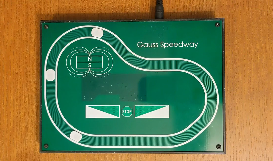
The best-known example is the Gauss Speedway, a maker project by Jeff McBride. It uses a custom printed circuit board as the track and tiny 3D printed cars fitted with magnets. When the board drives current through specific trace patterns, magnetic forces move the cars along the path. In other words, the board is not just the “road.” It is the motor, the controller, and the invisible hand giving the cars a little electromagnetic shove.
Traditional slot cars receive power through rails and use onboard electric motors. PCB racing cars flip that concept upside down. The vehicles can be extremely small because they do not need motors, batteries, or complex wiring. The intelligence and energy live in the track. The cars become simple magnetic passengers, which is rude if you are a tiny motor but fantastic if you are trying to build an elegant motion-control demonstration.
The Core Idea: Copper Traces Become A Linear Motor
The magic behind racing cars on a PCB is not really magic, although it does have the same effect on people standing nearby. It is electromagnetism. When electric current moves through a conductor, it creates a magnetic field around that conductor. When a magnet sits near that current-carrying trace, the magnetic field and the magnet interact. If the trace pattern and current timing are designed correctly, the magnet experiences a force that can push it forward.
Think of it as a flat, unrolled motor. A conventional electric motor spins because coils and magnets interact in a circular arrangement. A PCB track uses traces arranged in patterns so the magnetic interaction moves the car along a route instead of turning a shaft. That makes the system closer to a planar linear motor than a normal toy car drive system.
In the Gauss Speedway concept, the trace layout behaves somewhat like a bipolar stepper motor. Different phases are energized in sequence, and small current steps help create smoother motion. Instead of the car lurching forward like a nervous shopping cart, microstepping lets it glide around the track with more precision. Smoothness matters because at this tiny scale, a bump, a rough print edge, or a rebellious speck of dust can become the villain of the race.
Why Magnets Are The Tiny Engines
The cars in this kind of project are often 3D printed and fitted with very small permanent magnets. These magnets must be installed with consistent orientation. If one magnet faces the wrong way, the car may behave less like a race car and more like a confused refrigerator decoration.
The magnet orientation determines how the car responds to the magnetic fields generated by the PCB traces. If the field direction and current direction are coordinated, the car moves forward. Reverse something, and the force changes direction. This is why magnetic PCB motion projects are both satisfying and unforgiving: the physics is beautifully consistent, but it does not care about your feelings or your deadline.
Using magnets inside simple cars also reduces weight. A lighter vehicle is easier to move, needs less force, and puts less demand on the board’s current drivers. That matters because PCB traces have resistance, and resistance turns electrical energy into heat. Heat is useful for coffee and terrible for delicate electronics. Good design keeps current high enough for motion but controlled enough to avoid cooking the board like a tiny copper pancake.
The PCB Is Not Just A Board; It Is The Track Geometry
Designing a PCB race track is not the same as drawing a fun squiggly road and clicking “order boards.” The trace geometry decides where force is produced, how smoothly the car moves, and how well it stays centered. Curves are especially tricky. A car moving around a bend wants to drift outward. If nothing corrects it, the race becomes less Formula 1 and more “magnet exits stage left.”
One clever solution is the use of guard rail traces. These traces run along the sides of the path and produce forces that help push the car back toward the center. They act like invisible bumpers. Unlike plastic guard rails, they are part of the circuit itself, which is exactly the kind of elegant overengineering makers secretly adore.
Layer count also matters. A two-layer PCB can work for simple prototypes, but routing signals and power around a compact track can quickly become a puzzle that makes spaghetti look organized. A four-layer board gives the designer more routing freedom and can place useful copper layers closer to the surface, improving the interaction between the trace current and the car magnets. The downside is cost, because every extra PCB layer whispers, “Your hobby budget was cute.”
Current Control: The Quiet Hero Of PCB Racing
The spectacular part of PCB car racing is watching tiny vehicles zip around the board. The less glamorous but more important part is current control. The board must drive multiple current paths, often reversibly, and it must do so in a predictable way. That usually means using motor-driver-style circuits, H-bridge concepts, current sensing, inductors, capacitors, and firmware that knows when to energize each phase.
Current control is not optional. If the current is too low, the car sulks in place. If it is too high, the board may overheat or the movement may become jumpy. If the timing is wrong, the car may vibrate, stall, or attempt a career change into modern dance.
Good current control also allows microstepping. Microstepping divides each motion cycle into smaller increments by varying the current through the phases. This makes the magnetic force transition more gradually, creating smoother motion. For a display piece, that smoothness looks polished. For a race toy, it makes the car easier to control and more fun to watch.
Touch Controls And The Joy Of Integrating Everything
One reason projects like this feel so polished is that the controls can be built directly into the PCB. Instead of using a separate handheld controller, the board can include push buttons or capacitive touch pads. A copper pad on a PCB can become a touch-sensitive input when connected to a microcontroller designed to measure changes in capacitance.
This turns the entire project into a self-contained object. The track, controls, electronics, and decorative layout can all live on the same board. That is one of the big advantages of PCB-based design: copper can be functional, structural, and visual at the same time. In normal electronics, a trace is just a trace. In a project like this, a trace can be a motor winding, a lane boundary, a control button, and a design feature. Not bad for something usually hidden inside a plastic box.
How It Compares With Traditional Slot Cars
Traditional slot cars are wonderfully direct. A car has a motor. The track has a slot. Power comes through rails. You squeeze a controller, the car accelerates, and if you squeeze too hard, the car launches into the family dog’s personal space. It is simple, mechanical, and fun.
PCB racing is different. The car can be almost passive. The track does the hard work. This creates several advantages. The vehicles can be smaller. The motion can be precisely controlled by software. The board can potentially coordinate multiple cars, automated patterns, timing modes, or interactive effects. It also opens the door to unusual layouts that would be difficult with conventional slots and rails.
However, PCB racing also has limitations. The system can be more expensive to develop. The force available from PCB traces is limited. Heat must be managed. The cars need low friction and consistent magnet placement. Multi-car racing can become complicated because magnets attract or repel each other when they get close. Two tiny cars on a narrow magnetic track may behave like rivals, teammates, or clingy refrigerator magnets at a family reunion.
Why Makers Love This Kind Of Project
Racing cars on a PCB sits in the sweet spot between “educational” and “ridiculously cool.” It teaches real engineering concepts without feeling like homework. Anyone watching can ask useful questions: Why does the car move? Why does current direction matter? Why do curves need guard rails? Why did the second prototype cost more than expected? Why is the solder mask black? Is black faster? Obviously yes, emotionally speaking.
For electronics hobbyists, the project demonstrates PCB layout as a mechanical design tool. For robotics fans, it shows how motion can be moved off the robot and into the environment. For educators, it is a great way to explain magnetic fields, Lorentz force, current control, microstepping, and iterative prototyping. For designers, it proves that a circuit board can be a beautiful object rather than a green rectangle apologizing for itself.
Potential Applications Beyond Tiny Racing
Although PCB racing cars are delightful as a toy, the underlying idea has broader uses. Any time small objects need to move across a surface, PCB-based magnetic motion becomes interesting. Model railroads are an obvious example. At very small scales, putting motors inside trains can be difficult, unreliable, or impossible. Driving magnetic vehicles externally from a PCB-like track can remove the need for onboard motors and electrical pickup through tiny wheels.
Interactive displays are another possibility. Museums, trade-show booths, and classrooms could use PCB motion platforms to move tiny objects in repeatable patterns. Imagine a miniature factory model where parts glide along paths, a city display with cars moving under software control, or a science exhibit where visitors adjust current and watch magnetic motion change in real time.
There are also robotics research connections. Magnetic microrobots and small mobile robot systems often use external fields or patterned actuation surfaces. A PCB race track is not a medical microrobot platform, but it shares the same general idea: make the environment intelligent so the moving object can be simpler. That idea is powerful. Sometimes the smartest robot is not the one with the most electronics onboard; it is the one skating across a very clever floor.
Design Challenges That Make The Project Interesting
1. Trace Resistance And Heat
PCB traces are conductors, but they are not perfect conductors. Narrow traces carrying significant current create voltage drop and heat. A PCB race track designer must choose trace widths, copper weight, current limits, and duty cycles carefully. The goal is enough magnetic force without turning the board into a decorative hand warmer.
2. Smooth Motion Around Curves
Straight sections are easier than curves. A car moving around a bend needs lateral stability. Guard rail traces help, but their placement and current must be tuned. Too little correction and the car wanders. Too much correction and the motion feels harsh.
3. Mechanical Friction
The cars may be tiny, but friction still files a complaint. The underside of each car should be smooth, light, and consistent. A thin surface film can sometimes improve motion by reducing bumps from the PCB surface. At miniature scale, even small imperfections can matter.
4. Magnet Consistency
Every magnet should be installed in the same orientation and at a similar height. Inconsistent magnet placement can make one car fast, another slow, and a third one spiritually opposed to corners.
5. Firmware Timing
The board’s firmware controls how current moves through the phases. Timing, acceleration, deceleration, and current profiles determine whether the car glides, jerks, stalls, or yeets itself into the guard rail. Good software turns copper traces into choreography.
How A DIY Builder Might Approach A PCB Race Car Project
A beginner should not start with a giant four-layer Monaco-style masterpiece unless they enjoy expensive lessons. A smarter path is to build a simple straight test section first. Use a small magnet carrier, a short sequence of traces, and a current driver that can reverse polarity. Measure how much current creates useful motion and how warm the traces get.
Next, test a small loop. Add basic guard rail traces and experiment with car shape, magnet height, and surface material. Once the physics behaves, then design the polished version with controls, lights, lap timing, or multiple lanes. Iteration is not failure; it is the traditional mating dance of hardware development.
For software, start with slow movement and conservative current limits. Add acceleration profiles only after the car reliably completes a lap. For the mechanical side, print several car bodies and compare them. Lighter is usually better, but too flimsy can cause wobble. A tiny race car should be sleek, not emotionally fragile.
Why This Project Is Great For STEM Education
Racing cars on a PCB is a fantastic STEM teaching tool because it makes invisible physics visible. Students can see that current direction matters. They can observe how magnetic fields create motion. They can compare trace patterns, test different cars, and learn why engineering design involves tradeoffs instead of one perfect answer.
It also connects multiple disciplines. PCB layout teaches electronics. The car body teaches mechanical design. The controller teaches embedded programming. The movement teaches physics. The inevitable debugging teaches patience, humility, and the important life skill of not blaming the compiler for a backward magnet.
Unlike many classroom electronics projects, this one has immediate visual payoff. A blinking LED is nice. A tiny car moving around a circuit board is better. It gives learners a reason to care about copper geometry, current regulation, and firmware timing. The project says, “Physics is real, and also it can race.”
The Aesthetic Appeal Of A PCB Racetrack
Modern PCBs can be surprisingly beautiful. Solder mask colors, exposed copper, silkscreen artwork, castellated edges, and careful trace geometry can turn a board into a designed object. A PCB racetrack benefits from that visual language. The track can look futuristic, minimal, playful, or like a tiny science-fiction city viewed from orbit.
Because the traces are part of the visual design, the board can show its own function. The curves, lanes, control pads, and electronics are not hidden. They invite inspection. That transparency is part of the fun. You are not just watching a toy; you are watching the mechanism think out loud in copper.
Future Possibilities: Smarter Tracks, Faster Cars, Better Races
The future of PCB racing could get very interesting. A more advanced version might include sensors that detect car position, closed-loop control that adjusts current in real time, lap counters, sound effects, LED race signals, or multiple track modes. The board could run time trials, automatic demonstrations, or head-to-head games.
Closed-loop control would be especially powerful. Instead of assuming the car is where the firmware expects it to be, the board could measure position and correct errors. That would allow faster speeds, better reliability, and more complex behavior. It would also add complexity, because every feature in hardware politely brings three new problems as houseguests.
Another possibility is modular tracks. Smaller PCB sections could connect electrically and mechanically to create larger layouts. A modular system would let builders create custom race courses, educational kits, or interactive desktop toys. The challenge would be keeping current paths, alignment, and control timing consistent across board boundaries.
Experience Notes: What Building Or Testing PCB Racing Cars Feels Like
Working with a project like racing cars on a PCB is a special kind of fun because it looks simple from the outside and becomes wonderfully complicated the closer you get. The first emotional stage is confidence. You draw a track, place traces, add a driver circuit, and think, “This will probably work.” Hardware then smiles politely and prepares your lesson plan.
The first test is usually not a dramatic race. It is more likely a tiny magnet twitching on the board while everyone leans in as if watching a moon landing. That twitch is exciting because it proves the concept is alive. The car may not complete a lap yet, but the physics has answered the door.
After that, the tuning begins. You adjust current. You change timing. You test whether the car moves better with a smoother underside. You discover that one printed body is slightly warped. You realize that magnet orientation should have been marked before gluing. You say something calm and professional like, “Interesting,” while internally filing a formal complaint against past-you.
Curves tend to be the most educational part. On a straight section, the car may move nicely. Around a bend, it can drift, chatter, or stop. This is where guard rail traces become more than a clever idea. They become the difference between “beautiful demonstration” and “tiny car repeatedly attempts escape.” Tuning the side forces feels a little like setting up suspension on a real race car, except the shocks are invisible magnetic fields and the pit lane is your workbench.
Surface finish also matters more than expected. A PCB is flat, but it is not perfectly smooth at the scale of tiny magnetic cars. Solder mask, exposed copper, silkscreen, dust, and small board features can influence motion. A thin film or very smooth sliding surface can improve consistency. This is one of those practical lessons that does not sound glamorous but can transform the project from fussy to satisfying.
Testing different car bodies is equally rewarding. A lighter car may move more easily, but if it is too light or poorly balanced, it may rotate or wobble. A slightly heavier car may track better but require more current. Magnet placement affects everything. Once you start comparing designs, the workbench begins to resemble a miniature racing garage, just with more tweezers and fewer energy drinks.
The most enjoyable moment is when the car completes a clean lap. It is a small motion, but it represents a large stack of successful decisions: PCB layout, current control, firmware timing, mechanical printing, magnetic alignment, and patience. The car zips around the board, and suddenly the project stops being a collection of files and parts. It becomes a tiny machine with personality.
There is also a deeper lesson. Racing cars on a PCB shows that engineering creativity often comes from reassigning jobs. A PCB does not have to be just a circuit carrier. A track does not have to be just plastic. A motor does not have to be inside the vehicle. When you move functions around, new designs appear. Sometimes those designs are practical. Sometimes they are playful. The best projects are both.
So yes, racing cars on a PCB is a toy. But it is also an elegant demonstration of electromagnetism, PCB design, motion control, and maker imagination. It proves that copper traces can do more than connect chips. Given the right current, they can start a race.
Conclusion
Racing cars on a PCB is one of those projects that makes electronics feel alive. It takes the printed circuit board, usually the quiet backstage worker of modern devices, and turns it into the main event. By combining magnetic cars, controlled current, clever trace geometry, microstepping, and thoughtful mechanical design, a PCB can become a miniature racetrack where physics does the driving.
The idea is more than a novelty. It points toward broader possibilities in model railroads, interactive displays, educational tools, and small-scale robotics. It also reminds makers that the best projects often begin with a slightly unreasonable question: “Could the circuit board itself move the car?” In this case, the answer is yesand it looks fantastic doing it.
Note: This article was written for web publication and synthesized from real maker, PCB design, magnetic motion, motor-control, and capacitive-touch engineering references. Source links and citation placeholders were intentionally omitted from the article body as requested.