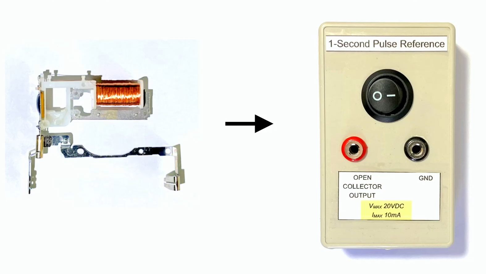
A quartz clock module is one of those humble little devices that usually gets ignored until it stops moving the hands on a wall clock. Then it is tossed into a drawer, a junk bin, or the mysterious “I might need this someday” box that every electronics hobbyist denies owning. But inside that cheap plastic movement is something surprisingly useful: a stable, low-power timekeeping circuit built around a 32.768 kHz quartz crystal.
With a little curiosity, a little soldering, and possibly a little muttering under your breath, that old clock module can be turned into a simple time reference. It will not replace a laboratory-grade atomic clock, a GPS-disciplined oscillator, or a temperature-controlled crystal oscillator. But for many bench projects, counters, data loggers, slow timing experiments, and educational builds, it can provide a practical 1 Hz reference signal that is cheap, quiet, and wonderfully satisfying.
This guide explains how a quartz clock module works, why the 32.768 kHz crystal matters, how to extract or condition its timing signal, where the limitations appear, and how to make the finished reference more useful. Think of it as electronic recycling with a punctual attitude.
What Is a Quartz Clock Module?
A quartz clock module is the compact electronic and mechanical assembly found in most battery-powered wall clocks. It usually runs from a single AA cell, drives a small stepper motor, and advances the second hand once per second. The magic is not really in the gears, although they deserve credit for surviving years of kitchen humidity and questionable dust. The real timing source is the quartz crystal.
Most clock modules use a 32.768 kHz tuning-fork quartz crystal. That number looks odd until you remember binary math: 32,768 equals 215. Divide the oscillator frequency by two fifteen times, and you get exactly 1 Hz. In plain English, the circuit counts 32,768 tiny vibrations of the crystal and turns them into one tick per second.
Why 32.768 kHz Is So Popular
The 32.768 kHz crystal became the standard for watches, real-time clocks, and small timekeeping devices because it balances accuracy, size, power consumption, and simplicity. A low-frequency tuning-fork crystal can run on very little current, which is ideal for devices expected to operate for months or years on a small battery.
In a traditional wall-clock movement, the circuit divides that crystal frequency down to alternating pulses that drive a coil. The coil nudges a permanent magnet rotor, the rotor turns gears, and the gears move the hands. The same signal that makes the second hand jump can be repurposed as a timing reference.
What Does “Time Reference” Mean Here?
A time reference is a signal used as a trusted timing source. In hobby electronics, that might mean a pulse once per second, often called 1 PPS, or a stable square wave used by a microcontroller, counter, clock display, or logger.
A GPS receiver with a 1 PPS output is a common choice because it can be extremely accurate when locked to satellites. A precision RTC module such as the DS3231 is another popular option because it includes a temperature-compensated oscillator and convenient digital features. A salvaged quartz clock module is less precise than those options, but it has a few appealing advantages: it is cheap, runs from low voltage, needs no antenna, and can work indoors, underground, or inside a metal box where GPS would sulk dramatically.
How the Clock Module Creates a One-Second Pulse
A typical quartz wall-clock movement contains three main timing stages: the quartz crystal oscillator, a divider chain, and a coil driver. The oscillator keeps the 32.768 kHz crystal vibrating. The divider chain reduces that high-frequency signal to a low-frequency pulse. The driver circuit sends current through the motor coil in alternating directions so the rotor steps forward.
The important detail is that many modules do not simply output a tidy logic-level square wave. Instead, they deliver short alternating pulses to the coil. One pulse may appear on one side of the coil, the next pulse on the other side, and the polarity flips every second. That is perfect for spinning a clock motor, but not always perfect for feeding directly into a microcontroller pin.
The Signal You Can Use
Depending on the module, the useful signal may be found at the motor coil terminals, at the divider output, or at a test pad if the manufacturer was feeling generous. The easiest method is usually to probe the two coil terminals with an oscilloscope or logic analyzer while the module is powered from its normal battery voltage.
You may see brief pulses once per second, alternating between the two coil pins. If you combine or condition those pulses, you can create a clean 1 Hz output. For some projects, simply detecting either pulse is enough. For others, you may want a proper square wave with consistent polarity, clean edges, and a defined voltage level.
Basic Parts and Tools
You do not need a luxury electronics bench to try this project. A basic setup can include an old quartz clock module, a fresh AA battery or regulated 1.5 V supply, a multimeter, a small soldering iron, thin wire, and ideally an oscilloscope or logic analyzer. If you do not have an oscilloscope, an LED tester circuit or a microcontroller interrupt input can help confirm that pulses exist, although measuring timing quality will be harder.
For signal conditioning, common parts include resistors, small-signal diodes, a transistor, a comparator, an optocoupler, or a logic gate with a Schmitt-trigger input. The best choice depends on what voltage your receiving circuit uses and how clean the pulse needs to be.
Step-by-Step: Turning the Module Into a Reference
1. Remove the Clock Movement Carefully
Start with a simple battery-powered quartz wall clock. Remove the hands gently, unscrew or unclip the movement, and open the plastic case if needed. Some modules snap apart easily; others behave like they were assembled by a tiny engineer with trust issues. Work slowly so you do not tear the coil wires or crack the circuit board.
2. Identify the Crystal and Coil
Look for the small cylindrical metal can or tuning-fork crystal marked around 32.768 kHz. Nearby will be a black epoxy blob or small IC, plus the copper motor coil. The two coil terminals are often the most accessible points for extracting a once-per-second signal.
3. Power the Module Properly
Most wall-clock modules are designed for one AA cell, so power them at about 1.5 V unless you know the circuit can handle more. A regulated supply is better for testing because supply voltage can affect some low-cost oscillator circuits. If you power the module from a bench supply, set a current limit. The goal is timekeeping, not making the world’s smallest smoke machine.
4. Probe the Output
Attach your oscilloscope ground carefully and probe the coil terminals. You may see narrow pulses that alternate once per second. Measure the pulse width, amplitude, and timing. If the pulses alternate polarity, your circuit must either detect both directions or convert them into one consistent output.
5. Condition the Pulse
A simple conditioning circuit can use two diodes to OR the alternating coil pulses into one node, followed by a resistor and transistor to create a logic-level output. A comparator or Schmitt-trigger input can clean up slow or noisy edges. An optocoupler can isolate the clock module from the rest of your circuit if ground loops or loading cause timing trouble.
6. Create a Usable 1 Hz Output
Once conditioned, the signal can be used as a 1 Hz pulse. A microcontroller can count rising edges, wake from sleep, update a display, timestamp slow events, or calibrate a rough internal oscillator. If you need a 50% duty-cycle square wave, feed the pulse into a flip-flop or generate a software square wave by toggling an output on each valid tick.
Accuracy: The Part Where Reality Clears Its Throat
Quartz clocks are impressively accurate compared with mechanical clocks, but they are not perfect. A common 20 ppm crystal can drift noticeably over days or weeks. One part per million equals about 0.0864 seconds per day, so 20 ppm can mean about 1.7 seconds per day under ideal conditions. Over a month, that adds up.
Temperature is one of the biggest villains. Watch crystals are usually cut to perform best around room temperature. As the temperature moves away from the turnover point, the frequency shifts. Aging, load capacitance, PCB leakage, supply voltage, and physical stress can also change the oscillator frequency. A clock module that is excellent for telling you when lunch is overdue may not be ideal for precision frequency measurement.
Good Enough Depends on the Job
For blinking an LED once per second, running a classroom timing demo, pacing a slow data logger, or giving a microcontroller a stable wake-up tick, a quartz clock module can be more than good enough. For calibrating radio equipment, measuring oscillator phase noise, disciplining a frequency counter, or building a serious time server, you should use a GPS-disciplined oscillator, a TCXO-based RTC, an OCXO, or another higher-grade reference.
How It Compares With a DS3231 RTC Module
The DS3231 is a popular real-time clock chip because it integrates a temperature-compensated crystal oscillator. Many breakout boards expose a 32 kHz output and a programmable square-wave output. Compared with a scavenged wall-clock module, the DS3231 is cleaner, more predictable, easier to interface with, and much better documented.
So why bother with the wall-clock module? Because hacking hardware teaches things that buying modules often hides. You learn how real clock movements drive coils, how alternating pulses behave, how loading affects a fragile oscillator circuit, and how a cheap consumer product squeezes years of operation from one battery. Also, there is a certain joy in turning a retired wall clock into test equipment. It is not exactly a superhero origin story, but it is close enough for the workbench.
Improving Stability and Reliability
Use a Stable Supply
If the oscillator changes slightly with supply voltage, a regulated supply can improve consistency. You can use a low-noise regulator or a carefully chosen battery arrangement. Avoid powering the module from a noisy digital rail without filtering. A clock circuit is patient, but it does not enjoy sharing a supply with motors, relays, or microcontrollers throwing current spikes like confetti.
Avoid Loading the Oscillator
Do not connect heavy loads directly to the clock circuit. The coil driver was designed for a tiny motor coil, not a collection of LEDs, long wires, and mystery breadboard capacitance. Use a high-impedance buffer, transistor, comparator, or optocoupler. If the clock slows down, stops, or behaves strangely after you connect your circuit, your interface is probably disturbing it.
Keep Temperature Reasonable
Keep the module away from heaters, direct sunlight, hot regulators, and drafty windows. If you need better stability, mount it in a small insulated enclosure. Some experimenters use a temperature-controlled oven for quartz references, but that is usually overkill for a salvaged wall-clock movement. Still, stable temperature equals more stable time.
Measure Before Trusting
Compare the output against a known reference over several hours or days. A GPS 1 PPS signal, NTP-synchronized system, frequency counter, or precision RTC can help characterize the clock module’s drift. Once you know its average error, you can compensate in software by occasionally skipping or adding a correction tick.
Practical Uses for a Quartz Clock Module Reference
A converted clock module can serve as a simple reference for microcontroller timing experiments. It can trigger a data logger once per second, act as a wake-up source for low-power projects, provide a heartbeat signal for a display, or help students visualize frequency division. It can also be useful in retrocomputing projects, homemade timers, art installations, and kinetic displays where a slow, steady pulse matters more than atomic accuracy.
It is also a good backup reference. Unlike GPS, it does not need a sky view. Unlike Wi-Fi time, it does not need a network. Unlike your phone, it will not distract you with notifications while you are trying to debug a transistor circuit.
Common Mistakes to Avoid
Expecting GPS-Level Accuracy
A quartz wall-clock module is convenient, not miraculous. It can be stable enough for many tasks, but it will drift. If your project requires sub-microsecond accuracy or long-term traceability, use a better reference.
Ignoring Alternating Pulses
Many clock movements drive the motor with alternating polarity. If your circuit only sees every other pulse, you may accidentally build a 0.5 Hz reference. That is excellent if your project lives in slow motion, but otherwise slightly embarrassing.
Running the Module at the Wrong Voltage
More voltage is not automatically better. These modules are designed for very low-power operation. Overvoltage can damage the circuit or shift behavior. Start with the voltage the clock originally used.
Skipping Signal Conditioning
Raw motor pulses may be narrow, low-voltage, or oddly shaped. A microcontroller might miss them, double-count them, or interpret noise as real ticks. Clean the signal before relying on it.
Experience Notes: What This Project Teaches in the Real World
Working with a quartz clock module is a great reminder that electronics does not always arrive as neat logic levels and friendly pin labels. The first surprise is usually the pulse shape. Many beginners expect to find a square wave that politely rises to 5 V and falls back to ground every second. Instead, they find tiny alternating pulses across a motor coil, sometimes only visible when the scope is set carefully. The module is not being rude; it was simply designed to move gears, not please a microcontroller.
The second lesson is that low-power circuits are delicate. A wall-clock movement may run for a year or more from a single AA battery because every part of the circuit is optimized to sip current. Add a load that seems harmless, and the timing may shift or the oscillator may stop. Long wires, breadboard capacitance, LED indicators, and direct connections to digital inputs can all influence behavior. Buffering is not just a fancy engineering habit here; it is the difference between a stable tick and a clock that looks personally offended.
Another useful experience is learning to separate precision from accuracy. The clock may tick with impressive consistency from one second to the next, yet still run a few seconds fast or slow per day. That makes it precise enough for certain local timing jobs but not accurate enough to be called an absolute standard. Once you compare it with GPS, NTP, or a good RTC, you start to see drift as a measurable personality trait rather than a failure.
Temperature testing is especially revealing. Place the module near a warm lamp, then move it to a cooler part of the room and monitor the long-term rate. The changes will not look dramatic second by second, but over hours they become visible. This is why precision timekeeping devices often use compensation, calibration, or controlled temperature environments. Your wall clock does not care if dinner starts seven seconds late, but your frequency counter might.
The project also teaches patience. Timing experiments are slow by nature. A bad amplifier circuit reveals itself instantly; a drifting time reference may take a day to confess. Keep notes. Record supply voltage, room temperature, pulse width, measured drift, and circuit changes. After a few test runs, you will understand the module far better than if you had only read a datasheet.
Finally, this hack is a satisfying example of practical reuse. An old clock movement is not glamorous, but it contains a crystal oscillator, divider logic, a coil driver, gears, and a mechanical display system that ran reliably for years. Turning it into a time reference gives that little circuit a second career. It may not become the master clock for a national standards lab, but it can become a useful bench tool, a teaching aid, or the heartbeat of a quirky embedded project. Not bad for something rescued from a clock that probably spent its life above a microwave.
Conclusion
Turning a quartz clock module into a time reference is not about building the most accurate clock on Earth. It is about understanding how everyday timekeeping works and repurposing a simple circuit into something useful. The 32.768 kHz crystal, divider chain, and motor pulses inside a cheap wall-clock movement can become a practical 1 Hz reference with the right interface.
The finished result is best viewed as a local timing source, not a precision standard. It can help with microcontroller projects, data logging, demonstrations, low-power timing, and experimental builds. With stable power, careful buffering, and basic calibration, it can be surprisingly useful. More importantly, it turns a forgotten clock module into a hands-on lesson in oscillators, frequency division, drift, and signal conditioning. That is a pretty good return from a piece of plastic that used to tell people they were late.