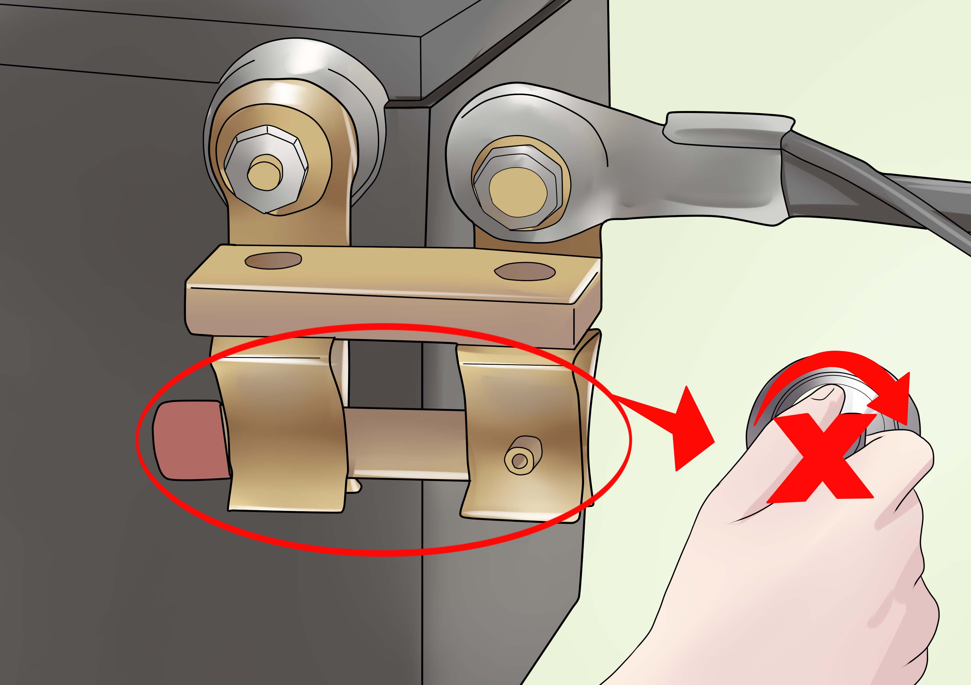
A car battery cut off switch is a small component with a surprisingly important job: it lets you separate the battery from the vehicle’s electrical system without repeatedly wrestling with a battery terminal. Installed correctly, it can reduce parasitic battery drain, simplify maintenance, add a basic layer of theft deterrence, and provide a rapid electrical shutdown in an emergency.
Installed incorrectly, however, a battery disconnect switch can become a high-resistance bottleneck, prevent the starter from cranking, damage electrical components, or fail to shut down a running engine. In other words, this is not the ideal project for the “red wire probably goes somewhere red-ish” school of automotive repair.
This complete guide explains how to attach a car battery cut off switch, select the correct type, size the cables, handle the alternator circuit, test the installation, and avoid the mistakes that cause most problems.
What Is a Car Battery Cut Off Switch?
A car battery cut off switch, also called a battery disconnect switch, master battery switch, isolation switch, or battery kill switch, opens the electrical connection between the battery and the vehicle. When the switch is on, current can flow normally. When it is off, the connected circuit is interrupted.
The exact result depends on how the switch is wired. A simple negative-terminal switch may disconnect most vehicle loads while the engine is parked. A properly designed race-car master switch can isolate the battery, alternator, ignition system, fuel system, and other electrical circuits so the engine stops immediately.
Common reasons to install one
- Prevent parasitic drain during long-term storage
- Make battery maintenance quicker and safer
- Add a visible or hidden theft-deterrent device
- Provide emergency electrical isolation
- Meet competition or track safety requirements
- Control auxiliary batteries in campers, work vehicles, or custom builds
A disconnect switch does not repair a weak battery or eliminate an underlying electrical fault. If the battery goes flat overnight, find the parasitic draw instead of asking the switch to serve as a tiny mechanical bandage forever.
Choose the Right Battery Disconnect Switch
Before reaching for a wrench, choose a switch suited to the vehicle and the purpose of the installation.
1. Terminal-mounted knob switch
This compact switch attaches directly to a battery post, usually the negative terminal. Turning the knob breaks the connection. It is inexpensive and useful for stored classic cars, recreational vehicles, lawn equipment, and vehicles with uncomplicated electrical systems.
Its limitations include lower current capacity, restricted battery-box clearance, and the inconvenience of opening the hood whenever power must be restored. Cheap versions may also loosen or corrode quickly.
2. Two-post manual master switch
A heavy-duty rotary or lever switch has two large terminals and is installed in series with a main battery cable. It is suitable for many street rods, off-road vehicles, boats, and custom electrical systems, provided its continuous and cranking-current ratings are high enough.
3. Keyed removable-handle switch
This design operates like a manual master switch but uses a removable key or handle. Removing it provides modest theft deterrence and prevents accidental operation.
4. Remote solenoid disconnect
A high-current solenoid is mounted close to the battery and controlled by a smaller switch inside the cabin or another accessible location. This reduces the length of heavy battery cable that must be routed to the dashboard. Confirm that the solenoid is rated for continuous service if it must remain energized while the vehicle operates.
5. Four-pole alternator-disconnect switch
Performance and competition vehicles often need a multi-pole switch or an alternator-shutdown relay. The large contacts interrupt the battery cable, while smaller contacts interrupt an alternator field, ignition, or control circuit. This arrangement prevents the alternator from continuing to power the engine after the main battery connection is opened.
Understand Switch Ratings Before Buying
The starter motor may draw several hundred amps, with a considerably higher momentary surge. A switch that looks sturdy but is rated for only 50 or 100 amps may overheat, create voltage drop, or weld its contacts together.
Check at least three specifications:
- Continuous rating: Current the switch can carry for an extended period
- Intermittent rating: Higher current allowed for a limited duration
- Cranking or starting rating: Short surge capacity for starter operation
Select a switch rated for the vehicle’s voltage and starting demand. Diesel engines, high-compression engines, winches, powerful audio systems, and relocated batteries can require significantly higher-capacity components.
Should the Switch Go on the Positive or Negative Cable?
Both arrangements exist, but they serve somewhat different purposes.
Negative-side installation
A simple storage disconnect is commonly attached to the negative terminal. Interrupting the chassis-ground connection disables most vehicle circuits and reduces the chance of accidentally shorting a wrench from a positive terminal to grounded bodywork during installation.
This approach is straightforward, but equipment with a separate ground path may remain connected. Trailer wiring, chargers, communication equipment, auxiliary batteries, or aftermarket accessories can create alternative paths.
Positive-side installation
Heavy-duty master switches are often installed in the positive cable, particularly in racing and custom-wiring applications. The cable from the battery positive terminal connects to one large switch stud, while the cable feeding the starter and electrical distribution system connects to the other.
A positive-side master switch must be protected against accidental contact. Use insulating terminal boots and mount the switch where its studs cannot touch metal panels, tools, cargo, or bodywork.
The alternator complication
Opening a basic battery switch while the engine is running may not stop the engine because the alternator can continue supplying the ignition and fuel systems. It can also create a voltage surge capable of harming electronics.
Do not turn a simple two-post switch off with the engine running. A running-engine shutdown test should be performed only when the system has been deliberately designed with an alternator disconnect, field interruption, shutdown relay, or manufacturer-approved multi-pole arrangement.
Tools and Materials
- Correctly rated battery cut off switch
- Battery cable equal to or larger than the original cable
- Properly sized copper cable lugs
- Adhesive-lined heat-shrink tubing
- Terminal boots or insulating covers
- Battery-terminal and combination wrenches
- Heavy-duty cable cutter
- Hydraulic, hammer, or professional-grade lug crimper
- Drill, bits, mounting hardware, and template
- Rubber grommets and abrasion-resistant cable loom
- P-clamps or insulated cable supports
- Digital multimeter
- Safety glasses and chemical-resistant gloves
Avoid using ordinary pliers to crimp large battery lugs. The connection may look acceptable while hiding enough resistance to produce heat, hard starting, and language unsuitable for the family garage.
How to Attach a Car Battery Cut Off Switch
Step 1: Review the vehicle and switch instructions
Confirm the battery location, terminal type, cable size, starter current, alternator layout, and factory power-management requirements. Determine whether disconnecting power will affect the alarm, radio code, power-window indexing, throttle adaptation, transmission learning, emissions monitors, or electronic keys.
If a memory saver is approved for the vehicle, connect it according to its instructions. Remember that a memory saver keeps parts of the electrical system energized, so it changes the normal assumption that the vehicle is completely powerless.
Step 2: Turn everything off
Park on a level surface, engage the parking brake, switch off the ignition, remove the key, and keep the key away from the vehicle. Turn off lights and accessories. Allow electronic modules to enter sleep mode when required by the manufacturer.
Step 3: Disconnect the battery safely
Disconnect the negative cable first and secure it where it cannot spring back onto the battery post. If the switch will be installed in the positive cable, disconnect the positive cable next.
Removing the negative cable first lowers the chance of creating a direct short if a tool touches grounded metal while loosening the positive connection.
Step 4: Choose the mounting location
Install a high-current switch as close to the battery as practical. Shorter cable runs reduce resistance, voltage drop, cost, and weight.
The location should be:
- Accessible for normal and emergency operation
- Protected from exhaust heat, moving components, and road debris
- Away from fuel lines and combustible materials
- Strong enough to resist vibration
- Large enough to provide clearance behind the panel
- Protected from water unless the switch is weather-resistant
For competition vehicles, position and label the external control according to the current rules of the applicable sanctioning organization. Do not rely on a decades-old forum post titled “This Passed Tech Once.”
Step 5: Plan the cable route
Measure the proposed cable route before cutting anything. Maintain clearance from headers, steering shafts, suspension components, driveshafts, sharp sheet metal, and moving pedals.
Pass cables through metal panels only with correctly sized grommets or bulkhead fittings. Support long runs with insulated clamps so vibration cannot saw through the insulation.
Step 6: Mount the switch
Use the supplied template whenever possible. Check behind the panel before drilling for hidden wiring, brake lines, air-conditioning lines, fuel lines, and structural components.
Drill the mounting holes, remove sharp edges, treat exposed metal against corrosion, and secure the switch with the provided hardware. Do not use the plastic switch body as leverage while tightening terminal nuts.
Step 7: Prepare the battery cables
Cut the cable cleanly without crushing the conductor. Slide the heat-shrink tubing onto the cable before installing the lug. Strip only enough insulation for the conductor to enter the lug barrel fully.
Crimp the lug with equipment intended for that cable size. Inspect the connection, perform a firm pull test, and seal it with adhesive-lined heat shrink. A proper crimp should be mechanically secure before heat shrink is applied.
Step 8: Connect a simple negative-terminal switch
For a terminal-mounted negative disconnect, the basic arrangement is:
Clean the battery post and cable terminal before assembly. Install the switch without forcing or twisting the battery post. Tighten the connections to the product specification and confirm that the switch does not interfere with the hood, battery cover, or hold-down bracket.
Step 9: Connect a two-post positive master switch
The basic engine-off arrangement is:
Connect the battery-side cable to one large stud and the vehicle-side cable to the other. Many two-post switches are electrically non-directional, but you should follow the markings and instructions supplied with the product.
Install insulating boots over both positive studs. Make sure no cable tension is pulling sideways on the switch terminals.
Step 10: Wire the alternator correctly when required
On a vehicle that must shut down while running, the alternator must not remain connected in a way that continues feeding the ignition and main electrical bus. Depending on the switch design, the solution may involve:
- Routing the alternator output to the battery side of the master switch
- Using a four-pole switch with dedicated small control contacts
- Interrupting the alternator field or regulator circuit
- Installing a properly rated alternator-shutdown relay
- Following a vehicle-specific motorsport wiring diagram
Alternator wiring varies considerably. Never guess which small wire should be interrupted, especially on late-model vehicles with computer-controlled charging systems.
Step 11: Reconnect the battery
Inspect every connection and remove tools from the engine compartment. Confirm that the switch is in the off position. Reconnect the positive terminal first, followed by the negative terminal.
Apply a suitable battery-terminal protectant where appropriate, but do not smear grease between electrical mating surfaces before tightening unless the component manufacturer directs you to do so.
Step 12: Test the system
Begin with the engine off:
- Turn the switch on and verify that normal electrical power returns.
- Check headlights, accessories, and the starter.
- Turn the switch off and confirm that the intended circuits lose power.
- Measure voltage across the closed switch while cranking.
- Inspect the switch and cables for warmth after several starts.
A meaningful voltage drop across the closed switch indicates excessive resistance from an undersized switch, loose terminal, poor crimp, corrosion, or damaged cable.
Perform an engine-running shutdown test only if the installation includes a correctly designed alternator and ignition shutdown circuit. The engine should stop, and the vehicle should not remain powered by alternator output.
Common Installation Mistakes
Using a switch with an inadequate cranking rating
A low-current accessory switch cannot safely carry starter current. It may overheat even when it appears to work during the first few starts.
Installing cable that is smaller than the original
Undersized cable increases resistance and voltage drop. Match or exceed the factory conductor size, particularly when adding cable length.
Leaving positive studs exposed
An exposed terminal can short against tools, luggage, body panels, or loose hardware. Use protective boots and covers.
Ignoring the alternator
A battery switch that disconnects the battery but leaves the running engine energized is not a functional emergency master cutoff.
Routing cables through bare sheet metal
Vibration can gradually cut through insulation. Every panel penetration needs a grommet, bulkhead fitting, or equivalent protection.
Creating an accidental bypass
Accessories connected directly to the battery may remain powered when the master switch is off. Map every cable attached to the battery, starter terminal, alternator, auxiliary fuse block, and secondary battery.
Disconnecting power on an unprepared modern vehicle
Loss of stored settings may trigger warning lights, relearn procedures, security problems, or battery-management errors. Check the service procedure first.
Troubleshooting After Installation
The starter clicks but does not crank
Check battery charge, switch rating, cable size, terminal tightness, crimp quality, and engine-ground straps. Measure voltage at the battery and starter while attempting to crank.
The switch becomes hot
Stop using the vehicle until the cause is corrected. Heat normally indicates high resistance, excessive current, loose hardware, contamination, or a switch that is too small.
The vehicle has no power with the switch on
Verify cable placement, terminal contact, switch position, battery voltage, main fuses, fusible links, and ground connections.
The engine keeps running with the switch off
The alternator is probably continuing to feed the vehicle. Do not repeatedly perform this test. Correct the alternator-shutdown wiring using the switch manufacturer’s diagram.
The battery still drains during storage
Look for a bypass circuit, a second battery, a charger ground, trailer wiring, or an accessory connected directly to the battery. The battery may also be internally damaged or self-discharging.
Maintenance Tips
Inspect the installation several times during the first month and at regular service intervals afterward. Check that mounting hardware remains secure, cables are not rubbing, terminal boots are intact, and no corrosion is forming.
Operate a manual switch periodically so its contacts do not sit untouched for years. After heavy cranking, winching, or high-current accessory use, carefully check for unusual warmth. Replace a switch that feels rough, loose, burned, or inconsistent.
Frequently Asked Questions
Will a battery cut off switch prevent battery drain?
It can prevent drain from circuits located on the disconnected side of the switch. It will not stop battery self-discharge, and it cannot isolate accessories that bypass the switch.
Can I install the switch on the negative terminal?
Yes. A negative-terminal switch is commonly used for storage and maintenance. Confirm that no alternative ground paths defeat the disconnect.
Can I turn the switch off while driving?
Not unless the system was specifically designed as a running-engine master cutoff with correct alternator protection. Opening a simple switch while the engine runs can create damaging voltage transients.
Does a battery disconnect switch stop theft?
It can make an unauthorized start more difficult, especially when hidden or fitted with a removable key. It should be treated as one layer of security rather than a complete anti-theft system.
Will disconnecting the battery erase settings?
It may erase radio presets, clocks, learned idle values, window positions, trip data, and other stored information. Some vehicles need additional reset or registration procedures.
Practical Experiences and Lessons From Real Installations
The following examples reflect recurring experiences reported by vehicle owners, restorers, racers, and installers. They are useful because battery-switch problems often appear only after the neat photographs have been taken and the toolbox has been triumphantly closed.
The weekend classic that kept losing its charge
A common situation involves a classic car driven only once or twice a month. The battery tests well, the alternator charges normally, and no dramatic electrical fault is visible. Yet the clock, aftermarket stereo, alarm, or aging wiring slowly drains the battery between drives.
Installing a negative-post knob switch can solve the storage problem quickly. The owner turns the knob off after parking and reconnects it before the next drive. The lesson is that convenience matters: a switch that takes two seconds to operate is more likely to be used consistently than a battery cable requiring tools.
The tradeoff becomes obvious after the first reconnection. Radio presets disappear, the clock flashes, and an electronic fuel-injection conversion may need a brief idle relearn. Some owners accept this inconvenience; others add a properly fused low-current memory bypass. Any bypass must be deliberately designed because it means the vehicle is no longer completely isolated.
The bargain switch that created a hard-start problem
Another familiar experience begins with a switch advertised as “heavy duty” but carrying no meaningful continuous or cranking-current specification. It works during initial testing, so everyone celebrates. Weeks later, the starter turns more slowly, and the switch feels warm after cranking.
Voltage testing reveals a substantial drop across the closed contacts. Replacing the unit with a switch carrying a suitable continuous and starting rating restores normal cranking. The practical lesson is simple: current ratings matter more than handle size, chrome plating, or the enthusiastic use of the word “professional” on the package.
The race car that refused to shut off
A rear-mounted battery and external two-post cutoff may appear correctly wired. With the engine off, rotating the switch removes power from the battery and starter. During the first running test, however, the engine continues happily idling with the switch off.
The alternator is still supplying the ignition and fuel system through the main electrical bus. The solution is not to keep testing until something surrenders. The solution is to reconfigure the charging circuit according to an approved diagram, often using a four-pole switch or alternator-shutdown relay. After correction, operating the master switch stops the engine and isolates the charging source as intended.
This experience demonstrates why an engine-off continuity test cannot prove that an emergency racing cutoff works. The alternator must be considered as an active power source whenever the engine is running.
The cable that looked perfect until it rubbed through
Relocated batteries create another lesson. A long positive cable may be secured neatly in the trunk but left unsupported where it passes beneath the rear seat or through a bulkhead. Months of vibration allow the insulation to rub against a metal edge.
The installation can be improved with a proper bulkhead fitting, abrasion-resistant loom, insulated clamps, and adequate clearance from moving parts. Cable protection is not decorative housekeeping. A shorted battery cable can release enormous current before a driver has time to reach the cutoff.
The modern car that needed more than a clock reset
On newer vehicles, disconnecting the battery may produce several warning messages after power is restored. Steering-angle calibration, window indexing, idle learning, transmission adaptation, security initialization, or battery-monitoring data may need attention.
Some warnings clear after an approved drive cycle, while others require a scan tool or manufacturer-specific procedure. The lesson is to research the exact vehicle before installation rather than assuming every 12-volt system behaves like a 1970s pickup. A battery cut off switch remains possible in many applications, but the design may need to preserve selected circuits or integrate with the factory energy-management system.
The most valuable habit: test instead of guessing
The best installation experiences share one habit: measurements are taken before and after the modification. Battery voltage is recorded, voltage drop is checked during cranking, charging voltage is verified, and the disconnected side is tested for unexpected power.
A multimeter cannot choose the correct switch or repair a poor crimp, but it quickly exposes assumptions. It turns “the cable looks fine” into a useful number and often finds a loose connection before heat, smoke, or a tow truck becomes part of the afternoon.
Conclusion
Learning how to attach a car battery cut off switch begins with selecting the right device, not drilling the first available panel. Match the switch to the vehicle’s cranking current, use full-size battery cable, protect every positive terminal, support the cable route, and account for the alternator whenever running-engine shutdown is required.
A simple negative-post disconnect may be all that a stored classic needs. A race car, relocated-battery build, or modern electronically managed vehicle can demand a much more deliberate system. When in doubt, use the switch manufacturer’s wiring diagram and have the completed circuit inspected by an experienced automotive electrician.
Done properly, a battery disconnect switch becomes one of those satisfying upgrades that quietly does its job for years. Done carelessly, it becomes a heated discussion between you, the starter motor, and a cable lug that was crimped with optimism.