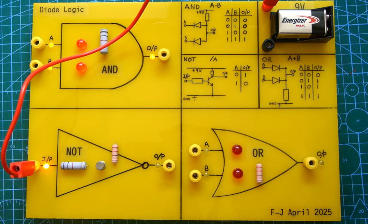
Before microcontrollers could blink LEDs, before programmable logic devices could do algebra faster than a tired engineer can find a missing jumper wire, digital electronics had to learn a very simple trick: make decisions with voltage. That trick is the heart of logic gates. And one of the most satisfying ways to understand it is by building diode and diode-transistor logic gates from ordinary components you can actually hold between two fingers.
Modern digital circuits usually hide their logic inside sleek black integrated circuits. A tiny CMOS chip can contain thousands, millions, or billions of transistors, all acting like microscopic traffic cops. But when you build a diode logic OR gate or a diode-transistor logic NAND gate on a breadboard, the mystery becomes beautifully visible. A diode conducts one way. A resistor pulls a voltage up or down. A transistor switches. Put them together correctly, and suddenly a handful of parts begins speaking Boolean.
This guide explains how diode logic and diode-transistor logic gates work, why they matter, how to build them, and what to watch for when the circuit behaves like it had coffee and you did not.
What Are Diode Logic Gates?
Diode logic, sometimes called diode-resistor logic or DRL, uses diodes and resistors to perform basic logic functions. The idea is simple: because a diode allows current to flow mainly in one direction, it can steer voltage signals in useful ways. With the right orientation and a pull-up or pull-down resistor, diodes can create OR and AND gates.
However, diode logic has one major limitation: it cannot easily create a NOT function by itself. A diode can guide current, but it cannot actively amplify or invert a signal. That means diode logic alone is not functionally complete. In plain English, it cannot build every possible digital circuit unless you add an active device such as a transistor. Diodes are excellent gatekeepers, but they are not magicians.
This is where diode-transistor logic, or DTL, enters the stage wearing a small but respectable engineering cape. DTL combines diode input networks with a transistor output stage. The diodes perform the input logic, while the transistor provides inversion and signal restoration. This made DTL an important historical step between early resistor-transistor logic and later transistor-transistor logic.
Why Build Logic Gates From Discrete Components?
You can buy a 74HC08 AND gate or a 74LS00 NAND gate for very little money, so why build gates from individual diodes, resistors, and transistors? Because it teaches the physical behavior behind digital logic. A commercial logic IC gives you a clean truth table. A breadboarded diode logic circuit shows you why the truth table happens.
Building diode and diode-transistor logic gates helps you understand voltage thresholds, forward voltage drops, fan-out, propagation delay, saturation, pull-up resistors, pull-down resistors, and noise margin. These are not just textbook decorations. They explain why real circuits sometimes fail, why outputs sag, why inputs load each other, and why “high” and “low” are not philosophical ideas but voltage ranges with consequences.
It also gives beginners a low-cost way to explore digital electronics. A few 1N4148 diodes, 2N3904 or 2N2222 NPN transistors, resistors, LEDs, and a 5-volt supply are enough to build working logic gates. The parts are cheap, forgiving, and available almost everywhere. Best of all, when something goes wrong, the circuit is small enough that troubleshooting does not require a detective board with red string.
The Basic Components You Need
For most small experiments in diode logic and diode-transistor logic, you can use common through-hole components. A typical parts list includes:
- 1N4148 or 1N914 small-signal diodes
- 2N3904, 2N2222, or similar NPN bipolar junction transistors
- Resistors such as 1 kΩ, 4.7 kΩ, 10 kΩ, and 47 kΩ
- LEDs for visual output indicators
- A 5 V DC power supply
- A solderless breadboard and jumper wires
- A multimeter for measuring voltages
- Optional: an oscilloscope for observing switching behavior
A 5 V supply is convenient because many classic logic families used 5 V systems. Still, these circuits are experimental and discrete, not drop-in replacements for modern CMOS or TTL logic chips. Treat them as learning circuits first. If you connect them to other digital devices, check voltage levels and current limits carefully.
Understanding Logic Levels
A logic gate interprets voltage as either a logical 0 or a logical 1. In a simple 5 V positive logic system, 0 V usually represents logic LOW, while a voltage near 5 V represents logic HIGH. Real circuits are less perfect. A HIGH might be 4.3 V instead of 5 V. A LOW might be 0.2 V instead of exactly 0 V. The important question is whether the next circuit recognizes the voltage correctly.
Diodes introduce a forward voltage drop, often around 0.6 V to 0.7 V for a silicon diode at typical currents. This matters because every diode stage can reduce the voltage available at the output. If you cascade several diode logic gates, the signal can degrade until the next stage no longer knows whether it is seeing a confident HIGH or a nervous maybe. That is one reason diode logic is educational and useful in simple cases, but limited for large systems.
Building a Diode OR Gate
A diode OR gate is one of the easiest logic gates to build. In positive logic, the output should be HIGH if input A or input B is HIGH. It should be LOW only when both inputs are LOW.
How the Diode OR Gate Works
Connect the anode of one diode to input A and the anode of another diode to input B. Tie both cathodes together at the output node. Add a resistor from the output node to ground. This resistor acts as a pull-down, keeping the output LOW when no input is HIGH.
When input A goes HIGH, its diode becomes forward-biased and conducts current into the output node. The output rises to approximately the input voltage minus the diode drop. If input B goes HIGH, the same thing happens through its diode. If both inputs are HIGH, both diodes may conduct. If both inputs are LOW, neither diode drives the output, so the pull-down resistor brings the output to ground.
| Input A | Input B | Output |
|---|---|---|
| 0 | 0 | 0 |
| 0 | 1 | 1 |
| 1 | 0 | 1 |
| 1 | 1 | 1 |
This circuit is wonderfully direct. The diodes act like one-way doors that allow any HIGH input to raise the output. Just remember that the output HIGH will not be a perfect 5 V. With silicon diodes, it may land around 4.3 V if the input is 5 V.
Building a Diode AND Gate
A diode AND gate can also be built with diodes and a resistor, but the orientation changes. For positive logic, the output should be HIGH only when all inputs are HIGH. If any input is LOW, the output must be LOW.
How the Diode AND Gate Works
Connect a pull-up resistor from the output node to the positive supply. Then connect the cathodes of the input diodes to the input signals and their anodes to the output node. In this arrangement, any LOW input forward-biases its diode and pulls the output LOW. Only when all inputs are HIGH are the diodes reverse-biased, allowing the pull-up resistor to raise the output.
| Input A | Input B | Output |
|---|---|---|
| 0 | 0 | 0 |
| 0 | 1 | 0 |
| 1 | 0 | 0 |
| 1 | 1 | 1 |
The diode AND gate is slightly less intuitive at first because a LOW input actively dominates the output. Think of the output as trying to float upward through the pull-up resistor. Any LOW input grabs it by the ankle and pulls it down. Only when every input lets go does the output rise.
The Limitation of Pure Diode Logic
Diode logic can create AND and OR gates, but it cannot invert a signal. Without inversion, you cannot directly build NAND, NOR, XOR, flip-flops, counters, or most practical digital systems. Another issue is signal degradation. Because diode drops reduce voltage levels, outputs may become weaker as gates are chained together.
Pure diode logic also has limited fan-out, which means one output may not be able to drive many inputs reliably. The resistors and diode networks load each other, and the more gates you connect, the more the voltage levels shift. In a classroom circuit with two LEDs, this may be charming. In a computer, it is a tiny electrical disaster waiting for a meeting invitation.
To move beyond those limits, you need a device that can amplify and invert. That device is usually a transistor.
What Is Diode-Transistor Logic?
Diode-transistor logic uses diodes for the input logic network and a transistor for inversion and output drive. A classic DTL NAND gate includes input diodes, resistors for biasing, and an NPN transistor used as a switch. When the transistor turns on, it pulls the output LOW. When the transistor turns off, a collector resistor pulls the output HIGH.
This combination solves the biggest problem of diode-only circuits. The transistor restores the output signal and creates the NOT operation. Since NAND and NOR gates are universal gates, DTL circuits can be used to build more complex digital systems.
Building a DTL NAND Gate
The NAND gate is a favorite in digital electronics because it can be used to build every other logic function. A two-input NAND gate outputs LOW only when both inputs are HIGH. In all other cases, the output is HIGH.
Basic DTL NAND Operation
In a typical positive-logic DTL NAND gate, the input diode network behaves like an AND stage feeding a transistor inverter. When all inputs are HIGH, the diode network allows base current to flow into the transistor. The transistor saturates and pulls the output LOW. When any input is LOW, current is diverted away from the transistor base through the corresponding diode. The transistor turns off, and the collector resistor pulls the output HIGH.
| Input A | Input B | Output |
|---|---|---|
| 0 | 0 | 1 |
| 0 | 1 | 1 |
| 1 | 0 | 1 |
| 1 | 1 | 0 |
A simple experimental DTL NAND gate can be built with two input diodes, one NPN transistor, a base resistor, a collector resistor, and a pull-up supply. The exact resistor values depend on the supply voltage, transistor gain, and desired current. For a 5 V breadboard circuit, values such as 10 kΩ for base biasing and 1 kΩ to 4.7 kΩ for the collector resistor are common starting points. If an LED is used at the output, include a current-limiting resistor. LEDs are wonderful indicators, but they are terrible at forgiving missing resistors.
Building a DTL NOR Gate
A NOR gate outputs HIGH only when all inputs are LOW. If any input is HIGH, the output goes LOW. In DTL, a NOR function can be implemented by arranging the input network so that any HIGH input drives the transistor on. Once the transistor conducts, it pulls the output LOW.
The NOR gate is also universal, meaning it can be used to build any logic function. In practical digital design, NAND and NOR are popular because they naturally combine logic with inversion. Transistors are very good at inverting, so circuit families often lean into that strength instead of fighting it.
Choosing Resistor Values
Resistor selection affects speed, power consumption, noise margin, and output drive. A smaller resistor allows more current and can make a node switch faster, but it also wastes more power and may overload components. A larger resistor saves power but can make transitions slower and outputs weaker.
For diode logic gates, pull-up and pull-down resistors often fall in the 4.7 kΩ to 47 kΩ range for simple experiments. A 10 kΩ resistor is a friendly default because it keeps current modest while still producing readable voltage levels. For transistor collector resistors, 1 kΩ to 10 kΩ can work, depending on whether you are driving only another transistor input or also lighting an LED.
When in doubt, calculate the current. With a 5 V supply and a 1 kΩ resistor, the current is roughly 5 mA before accounting for voltage drops. With 10 kΩ, it is roughly 0.5 mA. These are safe, manageable values for many small-signal experiments. The circuit will not become a supercomputer, but it also should not become a toaster.
Common Problems When Building Diode and DTL Gates
Wrong Diode Direction
The most common mistake is reversing a diode. Diodes are directional components, and the band on the diode body marks the cathode. If a diode OR gate behaves like a very stubborn piece of wire art, check the diode orientation first.
Floating Inputs
An unconnected input may pick up noise and drift unpredictably. Always tie unused inputs to a defined HIGH or LOW level through appropriate resistors or direct connections, depending on the circuit design. Floating inputs are where clean truth tables go to develop trust issues.
Forgetting Diode Voltage Drop
A silicon diode does not pass a HIGH signal perfectly. It usually subtracts part of the voltage. In a 5 V system, a diode-fed output may sit around 4.3 V. That might be fine for one stage, but cascading multiple stages can cause trouble.
Insufficient Base Drive
In a DTL gate, the transistor must receive enough base current to switch properly. If the output does not pull LOW enough, the transistor may not be saturating. Check the base resistor, input voltage, diode drops, and transistor pinout.
LED Loading
Adding an LED directly to an output can change the circuit behavior. Use a current-limiting resistor, and remember that the LED path draws current. If the gate works without the LED but fails with it, the indicator may be loading the output too heavily.
Diode Logic vs. DTL vs. TTL and CMOS
Diode logic is simple and elegant, but limited. DTL improves on it by adding transistor inversion and gain. Historically, DTL was important because it helped make digital logic more practical before transistor-transistor logic became dominant. TTL later improved speed, drive capability, and integration density by using transistors for both logic and amplification. CMOS eventually became the dominant technology for many modern digital systems because of its excellent power efficiency and scalability.
Still, diode and diode-transistor logic remain valuable for learning. They expose the analog reality under digital abstraction. Every HIGH and LOW is really a voltage. Every switching event takes time. Every component has limits. The breadboard may look simple, but it is teaching lessons that still apply inside modern chips.
Practical Applications of Diode and DTL Gates
Discrete diode logic is useful for simple signal combining, input protection, wired-OR behavior, and educational demonstrations. In low-speed control circuits, a diode network can combine multiple conditions without needing a full logic IC. For example, several fault signals can be diode-ORed so that any one of them activates a warning input.
DTL circuits are less common in new commercial designs, but they are excellent for understanding classic digital logic families. They also help hobbyists build simple decision circuits from scratch. If you are restoring vintage electronics, studying old computers, or teaching digital fundamentals, DTL is more than a museum piece. It is a bridge between component-level electronics and integrated logic design.
Safety and Measurement Tips
Use a regulated low-voltage supply, preferably 5 V, for beginner experiments. Avoid connecting breadboard logic directly to high-voltage circuits. Check transistor pinouts before wiring because different transistor packages may arrange collector, base, and emitter differently. Use a multimeter to confirm HIGH and LOW levels at inputs, outputs, and transistor bases.
If the circuit does not work, measure before guessing. Check the supply voltage. Check ground continuity. Measure the output with all input combinations. Then measure the transistor base voltage. A DTL NAND gate should show the transistor turning on only when all required inputs are HIGH. If the base voltage never rises enough, the input network or resistor values may be wrong. If the base voltage rises but the output does not fall, inspect the transistor orientation and collector resistor.
Example Project: A Two-Input Logic Demonstrator
A great beginner project is a small board that demonstrates OR, AND, and NAND gates side by side. Use two switches as inputs A and B. Add pull-down or pull-up resistors so each switch produces clean HIGH and LOW states. Feed those inputs into a diode OR gate, a diode AND gate, and a DTL NAND gate. Put an LED with a resistor at each output.
Now flip the switches and compare the LEDs to the truth tables. This project turns abstract Boolean logic into something visible. It also reveals real-world details, such as LED brightness changes, output voltage drops, and the importance of defined input states. In other words, it teaches you that digital electronics is not magic. It is analog electronics wearing a very confident name tag.
Experiences From Building Diode And Diode-Transistor Logic Gates
The first experience most builders have with diode logic is surprise. The circuit looks too simple to do anything intelligent. Two diodes and a resistor do not exactly scream “future of computation.” Yet when the output follows the OR truth table, the lesson lands immediately: logic is not stored in a mysterious chip; it is created by the way current is allowed or blocked.
One useful hands-on habit is to build the gate first without an LED, then measure the output voltage with a multimeter. Beginners often wire an LED as the output indicator and assume the LED tells the whole story. It does not. An LED only tells you that enough current is flowing to make light. A meter tells you whether the voltage level is actually suitable for another logic stage. This distinction becomes important when testing diode gates, because the output HIGH may be reduced by a diode drop.
Another memorable lesson comes from cascading gates. A single diode OR gate usually behaves nicely. Two stages may still work. But as you add more passive stages, the voltage levels can become less convincing. The output is no longer a bold digital statement; it becomes a polite suggestion. This is the moment when the value of the transistor becomes obvious. The transistor in DTL does not merely invert the signal. It restores authority to the output.
When building a DTL NAND gate, the transistor stage can feel confusing at first because the output appears “backwards.” All inputs HIGH turns the transistor on, but the output goes LOW. This is not a bug. It is the entire point of the inverter stage. Once that clicks, NAND logic starts to feel natural. You realize why engineers love NAND gates: they combine input decision-making with inversion in an efficient structure.
Breadboard layout also matters more than beginners expect. Long jumper wires, loose connections, and unclear power rails can create strange results. A circuit that fails at midnight may work perfectly in the morning after one jumper is moved from the wrong row. This is not because electronics enjoy drama, although the evidence is suspicious. It is because breadboards are mechanical systems as much as electrical ones. Good layout, short wires, and consistent color coding reduce mistakes.
Component variation is another real experience worth noticing. Not every diode drops exactly the same voltage. Not every transistor has the same gain. A circuit copied from a diagram may need small resistor adjustments to behave cleanly with your parts. This is not failure; it is engineering. The diagram explains the idea. The bench teaches the tolerances.
One of the best troubleshooting strategies is to test each section separately. For a diode OR gate, test each input diode by applying HIGH to one input at a time. For a diode AND gate, confirm that each LOW input can pull the output down. For a DTL NAND gate, check the diode network first, then the transistor base, then the collector output. Divide the circuit into small questions, and the answers usually stop hiding.
Finally, building these gates creates respect for integrated circuits. After wiring a few gates by hand, a small 14-pin logic IC suddenly looks like a miracle of convenience. But the discrete version gives you something the chip cannot: intuition. You see why pull-up resistors matter, why current paths matter, why voltage thresholds matter, and why digital logic is built on analog behavior. That intuition pays off later when designing, debugging, or simply understanding more advanced electronics.
Conclusion
Building diode and diode-transistor logic gates is one of the clearest ways to understand digital electronics from the ground up. Diode logic demonstrates how simple components can create AND and OR functions, while DTL shows why transistors are needed for inversion, amplification, and stronger output signals. These circuits may not replace modern CMOS chips, but they remain powerful teaching tools for anyone who wants to understand how logic really works beneath the surface.
Whether you are a student, hobbyist, repair enthusiast, or curious builder, these gates offer a hands-on path into the foundations of computing. They are inexpensive, approachable, and just complicated enough to be interesting. Build one, measure it, break it, fix it, and then build another. That is how digital logic becomes more than a truth table. It becomes a circuit you understand.
Note: This article is written for educational electronics projects using low-voltage DC circuits. Always verify component ratings, use current-limiting resistors with LEDs, and avoid connecting experimental breadboard logic directly to unknown or high-voltage systems.