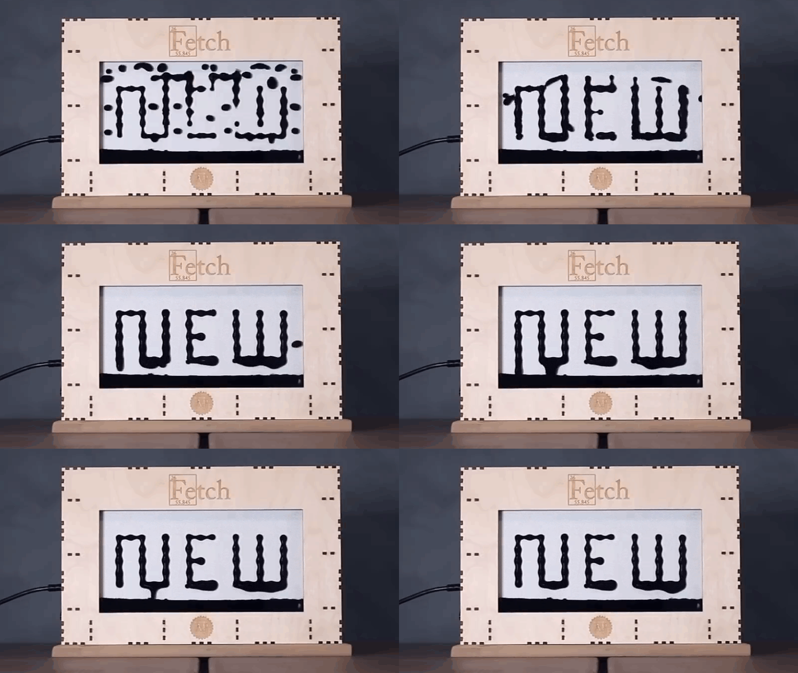
Some displays chase higher resolution. Others chase brighter colors. And then there is the ferrofluid display, which appears to have looked at ordinary screens, shrugged dramatically, and decided to become a living wall of magnetic black liquid instead. It is equal parts engineering challenge, science exhibit, and “wait, how is that even working?” moment.
The latest improvement behind this kind of display is not a prettier frame or a shinier demo video. It is better driver circuitry. That may sound about as glamorous as getting excited over a spreadsheet, but in this case the driver electronics are the difference between a mesmerizing ferrofluid display and a moody blob that slides downward like it has given up on life. When the circuitry improves, the whole display becomes more stable, more controllable, and more convincing as a real piece of interactive hardware.
In this article, we will unpack what changed, why it matters, and how a smarter driver design turns a fascinating prototype into something much closer to a polished engineering system. Along the way, we will also look at what ferrofluid is, why magnetic pixels are so stubborn, and what this upgrade says about the future of unconventional displays.
What Is a Ferrofluid Display, Exactly?
A ferrofluid display uses ferrofluid, a liquid containing tiny magnetic particles suspended in a carrier fluid, and manipulates it with an array of electromagnets. Ferrofluids were originally developed during the U.S. space program era, and the material has since found practical uses in seals, speakers, semiconductor manufacturing, and other specialized applications. In a display context, though, ferrofluid stops being merely useful and starts being theatrical.
Instead of pixels made from LEDs or liquid crystal cells, the screen uses magnetic “pixels” created by coils or electromagnets. When a coil energizes, it pulls and holds the ferrofluid into place. When multiple coils work together, the fluid can form letters, shapes, patterns, and animations. The result is slower than a conventional screen, but much more physical. You are not just seeing an image. You are seeing matter rearranged in real time.
That is precisely what makes a ferrofluid display so captivating and so difficult to engineer. Gravity is always in the room, acting like an uninvited critic. The fluid wants to fall. Neighboring magnets influence each other. The amount of force needed to hold one “pixel” is not always the same as the amount needed for another. In other words, this is not a simple on-off problem.
Why the Original Electronics Hit a Wall
One of the best-known open-source examples of this concept is Fetch, a project built around a 252-electromagnet matrix. In the project’s earlier architecture, the team relied heavily on shift registers and transistor arrays, which allowed them to expand control outputs but made fine-grained real-time control much harder. That first-generation approach was clever, but it forced the microcontroller to do too much of the heavy lifting in software.
And this is where the plot thickened. Unlike many matrix displays, a ferrofluid display cannot casually multiplex its outputs and hope everything will look okay. If an electromagnet drops out even briefly, the ferrofluid can fall away from that position. The project team found that the pixels needed continuous parallel drive, not quick turn-taking. That rule alone makes the electronics vastly more demanding than the usual hobby display project.
Then came the second challenge: one magnetic strength does not fit all. If several pixels in the same area or column are active, the ferrofluid redistributes itself under gravity and magnetic interaction. Lower pixels may steal fluid from upper ones. Adjacent magnets can affect flow. A clean image therefore requires not just activation, but control over the holding force of each electromagnet. That means pulse-width modulation, or PWM, becomes essential.
Software-generated PWM across a large matrix is possible in theory. In practice, it eats processing time, creates timing headaches, and turns firmware development into an endurance sport. A microcontroller can be brilliant, but asking it to babysit hundreds of magnetic channels with stable PWM timing is like asking one drummer to perform an entire marching band arrangement alone.
The Big Upgrade: Better Driver Circuitry
The new driver circuitry improved the ferrofluid display by moving PWM generation out of the processor’s overworked hands and into dedicated hardware. In the upgraded design, the project used the PCA9685, a 16-channel, 12-bit PWM controller commonly associated with LED control, paired with ULN2803 Darlington transistor arrays to handle the higher current needed by the electromagnets.
That choice was smart for several reasons. First, the PCA9685 provides hardware PWM over I²C, which means the controller can set duty cycles without manually bit-banging every pulse in software. Second, the ULN2803 can sink the current required by inductive loads far better than the PWM chip alone. Third, dividing control into row-level boards cleaned up the physical layout, shortened wire runs, and made the whole system less of a spaghetti festival hiding behind the display.
In plain English, the new circuitry gave the system more precision, less firmware stress, and a cleaner mechanical integration. Those three benefits matter more than they might seem. In hardware projects, elegance is not just aesthetic. It usually translates into reliability.
Why PWM Matters So Much Here
PWM works by switching power on and off rapidly, controlling the average current delivered to a load by changing the duty cycle. For inductive loads such as solenoids, motors, and electromagnets, PWM is a standard way to regulate holding force without resorting to bulky adjustable analog current systems. Texas Instruments and Analog Devices both describe PWM-based current regulation as a practical way to control inductive loads while balancing performance, efficiency, and heat.
That matters because a ferrofluid display is not merely trying to energize a coil. It is trying to create just enough magnetic pull to suspend and shape a living magnetic liquid under changing conditions. Too little force and the fluid sags. Too much and neighboring pixels may distort the image or accumulate fluid in the wrong place. PWM gives designers a finer steering wheel.
Why Protection and Current Control Matter
Every electromagnet is an inductive load, and inductive loads are famous for behaving politely right up until you switch them off. Then they try to throw voltage spikes back into the circuit. That is why flyback protection, current sensing, and thoughtful recirculation paths are so important in any serious electromagnet driver design. Engineering references from SparkFun, DigiKey, and major chip makers all point to the same lesson: ignore inductive kickback at your peril, and your MOSFETs or drivers may respond with smoke-based communication.
Even if a project does not use a full H-bridge on every channel, the design logic remains similar. Better driver circuitry is not just about turning magnets on. It is about managing current safely, consistently, and efficiently across many channels while minimizing thermal stress and electrical noise.
How the New Circuitry Improves the Display in Practice
So what does a better driver board actually buy you on-screen, or more accurately, in-tank?
1. More Stable Pixels
Because each electromagnet can be driven with more predictable PWM, the display can better maintain fluid at individual positions. That means text and patterns look more intentional and less like abstract expressionism produced by a tiny magnetic storm.
2. Better Compensation for Gravity
One of the hardest parts of a vertical ferrofluid display is the fact that gravity is always pulling the fluid downward. Adjustable hold strength allows the system to compensate for that effect, especially when multiple magnets in a column are active. Without this control, the lower sections can hoard the ferrofluid while upper sections start looking underfunded.
3. Cleaner Scaling
Dedicated row boards with built-in PWM make the system easier to scale and maintain. This is a major advantage for open-source hardware, where future builders need designs that are understandable, modular, and reproducible. A cleaner board layout also reduces wiring complexity and can improve troubleshooting.
4. Reduced Microcontroller Burden
Offloading PWM to dedicated chips frees the main controller for higher-level tasks such as animation logic, image processing, or communication. That is a huge architectural win. When one chip stops pretending to be twelve different jobs at once, the whole device usually becomes more responsive and more dependable.
5. A Better Path Toward Refinement
Once the driver circuitry is stable, engineers can focus on the next layer of improvement: tuning duty cycles, optimizing update strategies, refining fluid behavior, and experimenting with better algorithms for shaping images. In other words, the upgraded circuitry does not just fix today’s problem. It opens the door to tomorrow’s improvements.
Why This Project Matters Beyond the Niche
It would be easy to dismiss a ferrofluid display as a beautiful but impractical curiosity. That would be unfair. Projects like this often sit at the crossroads of art, controls engineering, materials science, and user experience. They test ideas that conventional product categories do not always make room for.
More importantly, they reveal what happens when digital control meets physical media. A ferrofluid display is not competing with OLEDs on pixel density. It is exploring a different question: what if a display were tactile, sculptural, and visibly mechanical in its behavior? What if the medium itself became part of the message?
That question has implications for museum installations, interactive art, educational exhibits, ambient information displays, and experimental interfaces. It also highlights a broader truth in engineering: breakthrough experiences often depend on unglamorous subsystem upgrades. The public sees the dancing fluid. The engineers know the real hero is the driver board tucked behind it.
The Engineering Lessons Hidden in the Black Goo
There are several takeaways from the “better driver circuitry” story, and they apply far beyond ferrofluid displays.
Use Dedicated Hardware When Timing Matters
If a task depends on stable, multi-channel PWM, dedicated controllers can save enormous development effort and deliver more consistent results than software timing alone.
Design for the Real Physics, Not the Ideal Diagram
In theory, each pixel might seem independent. In reality, gravity, adjacent fields, fluid dynamics, and mechanical lag all interact. Great hardware design starts when engineers stop fighting reality and begin designing around it.
Layout Is Part of Performance
The updated board form factor was not just tidier. It was functionally better. Cleaner routing, more logical connector placement, and boards designed around physical constraints often lead to fewer failures and easier iteration.
Inductive Loads Demand Respect
Electromagnets may look simple, but their behavior under switching conditions is anything but casual. Safe recirculation, proper transistor choice, protection components, and current management are not optional luxuries. They are the cost of admission.
What the Future Could Look Like
The next evolution of ferrofluid displays will probably involve even tighter current control, smarter feedback systems, and perhaps sensors that help the display adapt to how the fluid is actually behaving. More advanced driver architectures, current sensing, and closed-loop control could make these systems sharper and more repeatable.
That would not turn ferrofluid into a substitute for standard screens, nor should it. Its value lies elsewhere. It is slow in an interesting way. Physical in an age of flatness. Expressive in a way that pure pixels are not. Better driver circuitry does not make it ordinary. It makes it more fully itself.
Hands-On Experiences and Observations With Ferrofluid Display Driver Upgrades
Anyone who has spent time around a ferrofluid display quickly learns that this is not a project you casually “finish” over a quiet weekend with a soldering iron and a heroic level of optimism. It is the kind of build that teaches patience one magnetic hiccup at a time. The most memorable part is not always the final animation. It is the moment when a tiny change in duty cycle suddenly transforms a drooping, unreliable pattern into a crisp floating shape. That feels less like debugging and more like negotiating peace between physics and ambition.
One of the strangest experiences is how alive the system seems. Conventional electronics usually behave with predictable politeness: a logic high is high, an LED lights, a motor turns. Ferrofluid is different. It reacts with personality. Increase magnetic strength slightly and the fluid rises elegantly. Push too hard and it bunches, spikes, or crowds into neighboring regions like an impatient audience trying to get better seats. That is why improved driver circuitry matters so much at the practical level. Better control does not merely refine performance metrics. It makes the entire display feel less temperamental.
Builders also tend to notice that the wiring and board layout affect morale almost as much as they affect electrical performance. Early prototypes with tangled leads and awkward driver placements may still function, but they create constant friction. Every test becomes harder, every fault feels mysterious, and every repair requires the emotional resilience of a detective in a thunderstorm. Once the circuitry is reorganized into cleaner row-based boards with dedicated PWM hardware, the project becomes easier to trust. And in experimental hardware, trust is everything.
There is also a very human satisfaction in hearing that a microcontroller is no longer being forced to juggle an absurd software workload. Offloading PWM to dedicated chips sounds like an engineering footnote, yet it changes the development experience dramatically. Firmware gets simpler. Timing becomes more consistent. The display stops acting like it drank too much coffee. When that happens, you can spend more time exploring visuals and less time wondering which invisible scheduling conflict just wrecked your frame update.
Another practical observation is that ferrofluid displays reward incremental thinking. A better driver circuit does not magically erase all the quirks of fluid dynamics, magnetic interaction, or gravity. What it does is narrow the chaos. It shrinks the range of weird failures and turns the system into something engineers can tune instead of merely survive. That is often how real progress looks in advanced hobby and research hardware: not a dramatic leap from broken to perfect, but a series of upgrades that make the machine more understandable, controllable, and repeatable.
And finally, there is the audience reaction. When people watch a ferrofluid display for the first time, they usually do not ask about the PWM chip or the transistor array. They stare. They grin. They lean closer. Someone always says, “That looks fake,” which is the highest compliment a physical display like this can receive. But the builders know the truth. The magic is real, and it is built on current paths, protection strategies, layout choices, and better driver circuitry doing the unglamorous work. The black liquid gets the applause. The hardware earns it.
Conclusion
“Ferrofluid Display Gets New, Better Driver Circuitry” is more than a catchy project update. It is a reminder that unconventional hardware lives or dies by the quality of its supporting electronics. In the case of a ferrofluid display, the upgrade to dedicated PWM control and stronger driver architecture addresses the two biggest enemies in the system: inconsistent magnetic hold and too much software burden. The result is a display that is more stable, more controllable, and more compelling to watch.
That improvement matters because ferrofluid displays occupy a fascinating space between science and spectacle. They showcase how old materials and smart modern control electronics can create something that feels fresh, physical, and almost alive. Better driver circuitry does not merely improve the engineering behind the scenes. It enhances the visual experience, expands the system’s practical potential, and proves once again that in advanced hardware, tiny electrical decisions often create the biggest visible results.